
Brush-commutated electric motor

A technology of electric motors and motors, applied in the direction of electric components, DC commutators, electrical components, etc., can solve problems such as electromagnetic interference and interference

Inactive Publication Date: 2009-11-25
WABCO EURO BVBA SPRL
View PDF0 Cites 8 Cited by
  • Summary
  • Abstract
  • Description
  • Claims
  • Application Information

AI Technical Summary

Problems solved by technology

Disadvantage: Brush-commutated DC motors generate electromagnetic interference in the area where the brushes and commutator segments are located
However, the disadvantage of this known solution is that this shielding only extends to a certain printed circuit, so to speak only avoids the coupling of disturbances into the circuit
According to the existing technology, this solution still does not prevent the interference of the commutator system from spreading outward from the motor cylinder and interfering with the operation of other sensitive electronic components or radio receivers

Method used


Image

  • Brush-commutated electric motor
  • Brush-commutated electric motor
  • Brush-commutated electric motor

Examples


Embodiment Construction

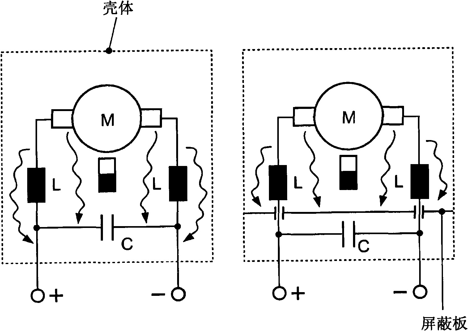
[0015] figure 1 (a) shows a schematic diagram of the working principle of the present invention. Electromagnetic interference is thus generated at the commutator in the electric motor M, which is drawn by a curved arrow. This electromagnetic interference is dissipated on the interference suppression element, which is represented here in a simplified form by a winding L and a capacitor C. In addition, due to the high-frequency part of electromagnetic interference, the interference passes by L and C on the anti-interference component and is also transmitted to circuits other than the electrical components L and C. figure 1 (b) shows a device with a shielding plate according to the invention exactly in a schematic representation. Interference that does not propagate along the line, especially from the area of ​​the commutator, therefore no longer propagates outside the area of ​​the shielded motor. The advantageous aspects of the invention are therefore based on the conclusion...


PUM


Abstract

The invention relates to an electric motor comprising a commutator and a corresponding commutator brush (32), a motor housing (1) that partly encloses the movable motor elements, and a brush rocker (5). Said electric motor is characterized by a sheet metal shield (21) for electromagnetically shielding the commutator and the commutator brushes (32). The sheet metal shield (21) is disposed further away from the motor than the brush rocker (5), separately and two-dimensionally covers substantially the entire brush rocker, and is connected in an electrically conductive manner to the motor housing.

Description

technical field [0001] This invention relates to electric motors, especially brush commutated electric motors. Background technique [0002] A brush-commutated DC motor firstly has a stator and a rotor mounted on the motor shaft, the rotor being moved inside the stator by a commutated magnetic field. In addition, electric motors of this type have a commutator arrangement consisting of commutator segments which can be fixedly mounted on the motor shaft and brushes which brush over the commutator segments. These brushes are arranged on top of so-called brush holders, which are fixedly connected to the motor housing. The brushes and the commutator segments interact in this way when the motor shaft rotates to achieve commutation or current commutation. Current commutation is essential to the rotational motion of a DC driven electric motor. The frequency of current commutation is proportional to the rotational speed of the motor shaft and depends on the number of pole pairs. ...

Claims


Application Information

Patent Timeline
Patent Type & Authority Applications(China)
IPC IPC(8): H02K11/02H02K23/66
CPCH02K11/022H02K23/66H02K5/148H02K11/026H02K11/0141
Inventor 汉斯-于尔根·弗兰克尼科·赫茨伯格克劳斯-维尔纳·施米特
Owner WABCO EURO BVBA SPRL
Learn More