
Electromagnetic heat-conduction oil type single wood plate drying machine

A technology of wood veneer and heat-conducting oil, which is applied in the field of dryers, can solve the problems of uneven water content of wood veneer, environmental pollution caused by burning coal, and difficulty in quality assurance, achieving convenient and quick snow removal, high drying efficiency, Easy to control effects

Inactive Publication Date: 2014-09-03
SUZHOU CHUANGWEISHENG AUTOMATION SCI & TECH
View PDF8 Cites 2 Cited by
  • Summary
  • Abstract
  • Description
  • Claims
  • Application Information

AI Technical Summary

Problems solved by technology

The traditional drying method is to dry the rotary-cut wood veneers one by one in the sun, and dry the wood veneers through water evaporation. However, the disadvantage of this drying method is that it takes up a lot of space and the production efficiency Low, the wood veneer after drying is easy to roll and deform, the quality is difficult to guarantee, and it is also subject to weather conditions
Nowadays, many wood veneer manufacturers use drying equipment to dry wood veneers. The drying equipment used is earth kiln, which is baked by fire. Although the dough can be dried in this way, The water content of the finished wood veneer is very uneven, the quality is still difficult to guarantee, and the burning of coal is also polluting the environment, which is not conducive to environmental protection and energy saving and emission reduction

Method used


Image

  • Electromagnetic heat-conduction oil type single wood plate drying machine
  • Electromagnetic heat-conduction oil type single wood plate drying machine

Examples


Embodiment Construction

[0011] In order to make the technical means, creative features, objectives and effects achieved by the present invention easy to understand, the present invention will be further described below in conjunction with specific illustrations.

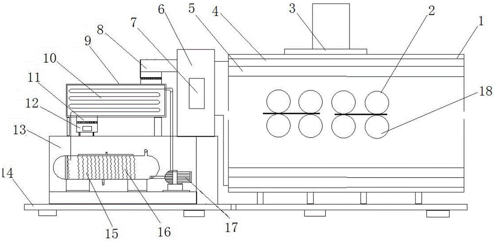
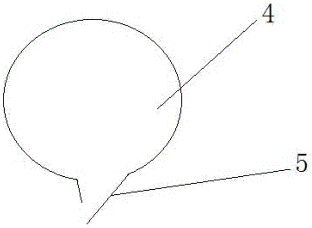
[0012] Such as figure 1 A kind of electromagnetic heat-conducting oil type wood veneer dryer shown, comprises the hot air device and oven 1 that are arranged on frame 14, and one end of oven 1 is provided with feed inlet, and the other end is provided with outlet, and oven 1 The top of the oven 1 is provided with a moisture outlet 3; the oven 1 is horizontally provided with a plurality of roller groups, and each roller group includes a corresponding upper roller 2 and a lower roller 18, wherein the lower roller 18 is the driving roller driven by the power device; the upper and lower ends of the oven are provided with four sets of hot air pipes 4 along the direction of roller group conveying, and the lower ends of the hot air pipes 4 are int...


PUM


Abstract

The invention provides an electromagnetic heat-conduction oil type single wood plate drying machine. The electromagnetic heat-conduction oil type single wood plate drying machine comprises a hot air device and a drying box which are arranged on a rack, wherein a feeding opening is formed in one end of the drying box and a discharging opening is formed in the other end of the drying box; a moisture discharging opening is formed in the top of the drying box; the drying box is internally and horizontally provided with a plurality of roller sets; the hot air device comprises a hot oil tank which is arranged at the lower end of an engine body and a heat exchanger arranged at the upper end of the engine body; the hot oil tank is internally provided with a plurality of sets of electromagnetic heating coils; a high-temperature circulating pump is arranged at one side of the hot oil tank; the heat exchanger is internally provided with a heat exchanging coiled pipe; a hot air outlet pipe and a lower-end pipeline of a roller drying machine body are communicated with an air storage chamber; the air storage chamber is provided with a pressurizing machine; the air storage chamber is connected with a hot air pipe through a pipeline. Compared with the prior art, the drying machine can be used for uniformly drying; a wood plate is not raised in a drying process; the drying efficiency is high; the electromagnetic heat-conduction oil type single wood plate drying machine is convenient to control and free from pollution.

Description

technical field [0001] The invention relates to a drying machine, in particular to an electromagnetic heat conducting oil type wood veneer drying machine. Background technique [0002] Wood veneer, also known as veneer and veneer, is mainly used to produce artificial wood panels such as plywood, blockboard, formwork, and veneer. Wood veneer is divided into two types: rotary cutting and planing, and the veneer used for wood-based panels is mostly rotary cutting. Because the wood veneer produced by rotary cutting contains a lot of water, it needs to be dried before it can be used to produce artificial wood panels. The traditional drying method is to dry the rotary-cut wood veneers one by one in the sun, and dry the wood veneers through water evaporation. However, the disadvantage of this drying method is that it takes up a lot of space and the production efficiency Low, the wood veneer after drying is easy to roll and deform, the quality is difficult to guarantee, and it is ...

Claims


Application Information

Patent Timeline
IPC IPC(8): F26B15/12F26B21/00
Inventor 田银东
Owner SUZHOU CHUANGWEISHENG AUTOMATION SCI & TECH
Learn More