Eureka AIR delivers breakthrough ideas for toughest innovation challenges, trusted by R&D personnel around the world.

Reduction gear with combination of gear change structure and eccentric cycloidal roller pin gear change structure

A variable speed structure and eccentric swing technology, applied in gear transmission, gear vibration/noise attenuation, transmission, etc., can solve the problem of complex structure and assembly process of cycloidal pinwheel reducer, reduced mechanical stability, increased wear of parts, etc. problem, to achieve the effect of compact structure, large overlapping coefficient and long life

Inactive Publication Date: 2014-09-03
四川奥斯廷科技有限公司
View PDF7 Cites 11 Cited by
  • Summary
  • Abstract
  • Description
  • Claims
  • Application Information

AI Technical Summary

Problems solved by technology

[0003] The traditional cycloidal pinwheel deceleration device relies on the geometric sliding of the circular arc profile of the cycloidal wheel and the circle of the outer needle for transmission and limit. The arc gradually disengages. Due to the actual machining error, the cycloidal wheel and the needle roller will always have a slight impact, which will result in reduced mechanical stability, increased noise, and increased wear of the parts.
In order to restore the normal operation of the reducer, the following methods are usually adopted: replace the cycloidal wheel, because the precision of the parts is high and the process is complicated, and the structure and assembly process of the cycloidal pinwheel reducer are also complicated, so the economy is poor

Method used


Image

  • Reduction gear with combination of gear change structure and eccentric cycloidal roller pin gear change structure
  • Reduction gear with combination of gear change structure and eccentric cycloidal roller pin gear change structure
  • Reduction gear with combination of gear change structure and eccentric cycloidal roller pin gear change structure

Examples


Embodiment Construction

[0020] The present invention will be described in further detail below in conjunction with the accompanying drawings.

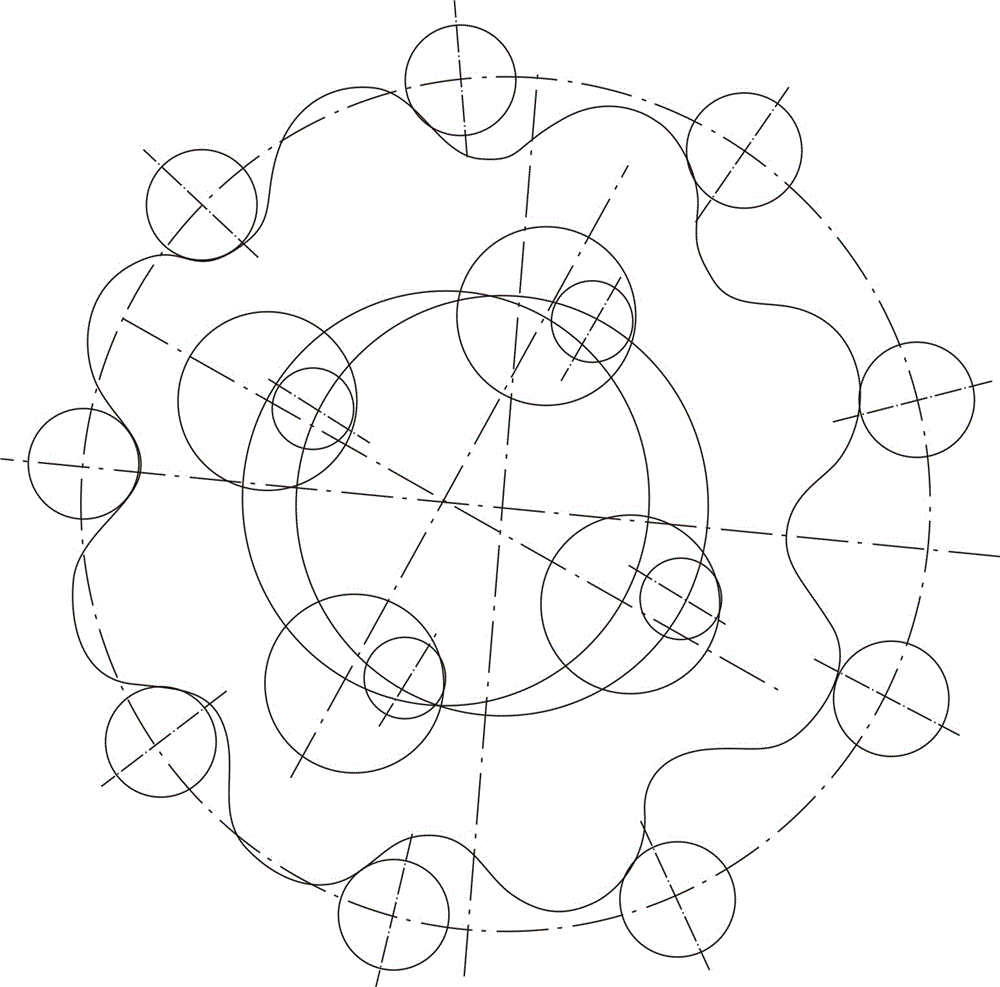
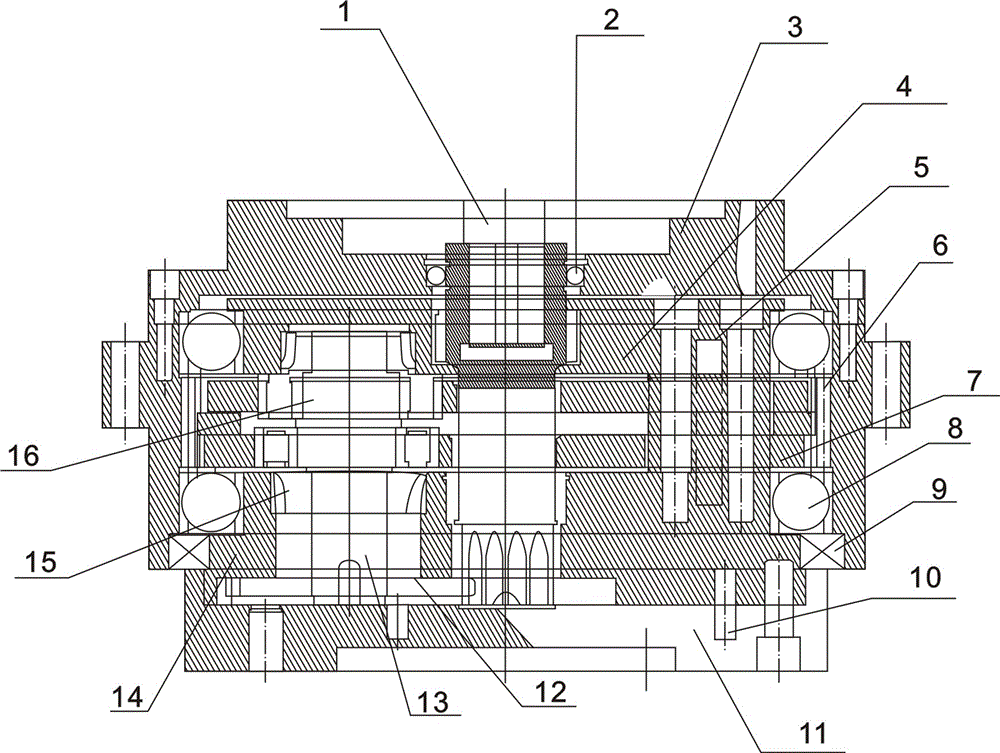
[0021] The entire transmission device of the new speed reduction device can be divided into three parts: input part, deceleration part and output part. First, the sun gear on the 1-input shaft drives three 12-planetary gears as the first-stage deceleration, and a pair of 180° double eccentric structures are designed on the three planetary gears 12-, and each section of eccentric cylinder is equipped with two The 16-bearing IV called the rotating arm drives two 7-cycloidal wheels to rotate, the eccentric cycloidal wheel is connected with the 4-bearing cover, and the 14-bearing sleeve is connected by bolts (4-bearing cover, 14-bearing sleeve outer shell and 8-Bearing II has a limited position and stabilizing effect on the internal cycloidal wheel, which greatly improves the stability of the internal mechanical movement and reduces noise) and through the structu...


PUM


Abstract

The invention relates to a gear eccentric cycloidal roller pin reduction gear, in particular to a reduction gear with the combination of a gear change structure and an eccentric cycloidal roller pin gear change structure. A composite 2-level reduction gear with the combination of a planetary gear structure and an eccentric roller pin structure is designed. The reduction gear is composed of an input part, a speed reduction part and an output part. The reduction gear is characterized in that a spur gear planetary mechanism without an outer gear ring is used for first level speed reduction, a sun gear on the input shaft drives three planetary gears to be used for achieving first level speed reduction, a pair of double-eccentric structure which is misplaced by 180 degrees is arranged on the three planetary gears, and two bearings, namely rotating arms, are arranged on each segment of eccentric cylinders to be used for driving two cycloidal gears to rotate. The reduction gear has the advantages of being high in reduction ratio and high in efficiency, the single-level transmission can reach the reduction ratio of 1:3, the efficiency reaches 90%, and if multi-level transmission is adopted, the reduction ration will be greater.

Description

technical field [0001] The invention relates to a gear eccentric pendulum needle roller deceleration device, in particular to a deceleration device combining a gear speed change structure and an eccentric oscillating needle roller speed change structure. Background technique [0002] Common oscillating reduction devices in the market today, such as cycloidal pin gear reduction, are based on a planetary transmission structure with a small tooth difference. First, the inner equidistant curve of the luffing epicycloid is used as the planetary gear profile curve and the circle is used as the center wheel. The tooth profile curve is the same as the involute small tooth difference planetary transmission mode, and the z-X-F type N-type planetary gear transmission is reserved. This structure can obtain a large reduction ratio, small size, relatively low noise, and high transmission efficiency. Compared with ordinary involute gears, there will be no tooth tip interference phenomenon...

Claims


Application Information

Patent Timeline
IPC IPC(8): F16H1/32
CPCF16H49/001F16H1/32F16H57/0006F16H2001/323
Inventor 李照廷
Owner 四川奥斯廷科技有限公司
Why Eureka
Eureka Blog
Learn More