
Reciprocating heat accumulating type internal combustion engine for air inlet and air outlet through scavenging duct

A scavenging channel and regenerative technology, which is applied to combustion engines, fuel heat treatment devices, combustion air/combustion-air treatment, etc., can solve the problems of low efficiency of gasoline engines, low efficiency of variable working conditions, and pollution of internal combustion engines. The effects of complete combustion, low vibration and noise, and reduced pollutant emissions

Inactive Publication Date: 2014-09-03
杨浩仁
View PDF4 Cites 2 Cited by
  • Summary
  • Abstract
  • Description
  • Claims
  • Application Information

AI Technical Summary

Problems solved by technology

[0005] In order to overcome the problems of low efficiency of gasoline engines, heavy diesel engines, serious pollution of internal combustion engines, low efficiency of variable working conditions, serious noise and vibration, many moving parts, frequent maintenance, etc., the present invention proposes an air intake and exhaust system using the scavenging channel. reciprocating regenerative internal combustion engine

Method used


Image

  • Reciprocating heat accumulating type internal combustion engine for air inlet and air outlet through scavenging duct
  • Reciprocating heat accumulating type internal combustion engine for air inlet and air outlet through scavenging duct
  • Reciprocating heat accumulating type internal combustion engine for air inlet and air outlet through scavenging duct

Examples


Embodiment Construction

[0022] Now in conjunction with the accompanying drawings, the present invention will be further described by taking specific implementation as an example.

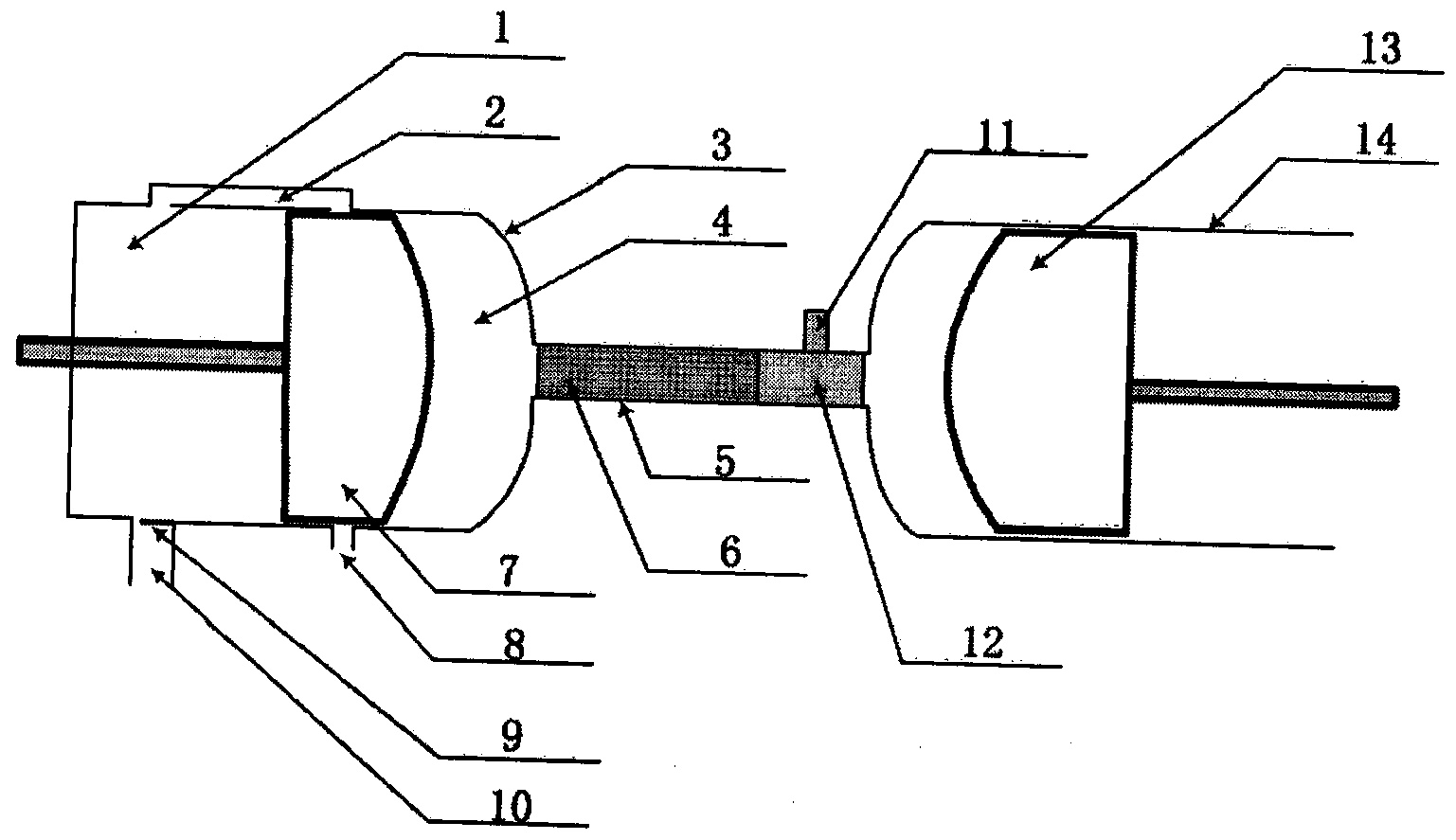
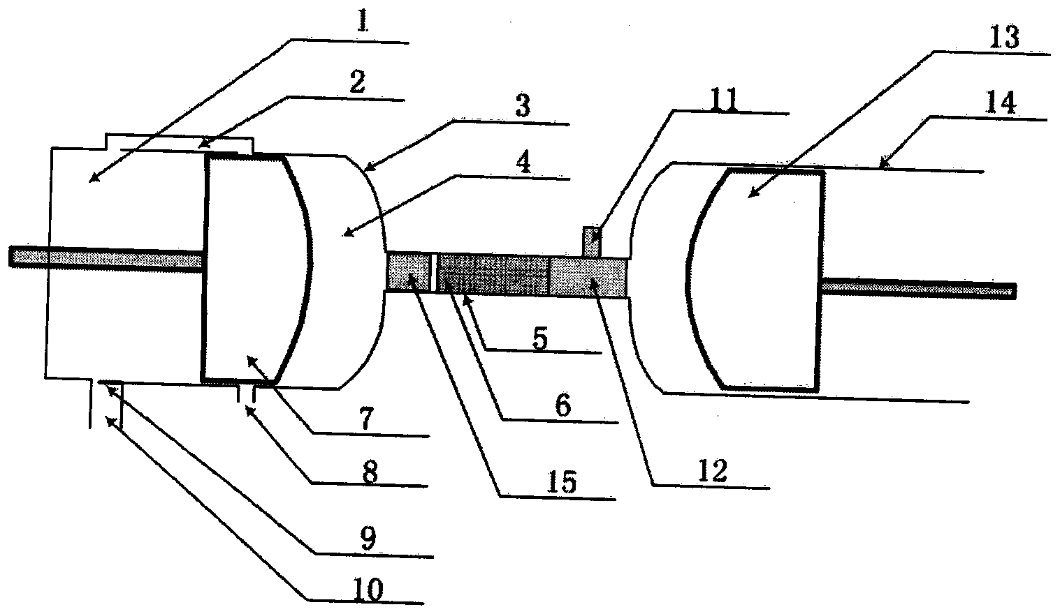
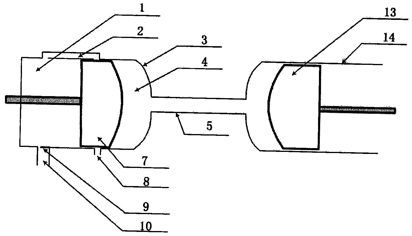
[0023] Such as figure 1 As shown, the reciprocating regenerative internal combustion engine mainly includes a compression cylinder 3 , a communication pipe 5 , a heat storage body 6 , a combustion chamber 12 and an expansion cylinder 14 . The connection mode of the compression cylinder 3, the connecting pipe 5 and the expansion cylinder 14 is as follows: image 3 shown. The compressed gas outlet of the compression cylinder 3 is connected to one end of the communication pipe 5 , and the other end of the communication pipe 5 is connected to the expansion cylinder 14 . The connection port between the communication pipe 5 and the expansion cylinder 14 serves as the intake and exhaust port of the expansion cylinder 14, that is, the gas entering and discharging of the expansion cylinder 14 passes through this connection port. ...


PUM


Abstract

A reciprocating heat accumulating type internal combustion engine for air inlet and air outlet through a scavenging duct comprises a compression air cylinder, a heat accumulator, a communicated pipe, a combustion chamber and an expansion air cylinder. The reciprocating heat accumulating type internal combustion engine is characterized in that the heat accumulator is located in a channel of the communicated pipe connecting the compression air cylinder and the expansion air cylinder, the compression air cylinder is divided into a pre-compression cavity and a compression cavity through a piston, and the pre-compression cavity and the compression cavity are connected through the scavenging duct. According to the basic operating principle, when the piston of the compression air cylinder moves towards the upper stopping point from the lower stopping point, the air is fed into the pre-compression cavity, the air in the compression cavity is compressed, the compressed air flows through the heat accumulator to be heated and enters the combustion chamber to be burned with the fuel, a piston of the expansion air cylinder moves downwards from the upper stopping point, and fuel gas expands and acts. When the piston of the air cylinder moves upwards, the piston of the compression air cylinder moves downwards, the acting fuel gas gets out of the expansion air cylinder and reversely passes a combustor and the heat accumulator reversely to heat the heat accumulator, the fuel gas temperature is reduced, the fuel gas enters the compression cavity and is exhausted through an exhaust outlet, fresh air enters the compression cavity through the scavenging duct, and a power circulation is finished.

Description

technical field [0001] The invention relates to an engine, which is a reciprocating regenerative internal combustion engine utilizing a scavenging channel for intake and exhaust. Background technique [0002] The engine generally refers to a heat engine, which is a power device that converts fuel or other energy into heat energy of the working medium inside the engine, and further converts it into mechanical energy. The internal combustion engine is a traditional and widely used engine, which has important applications in industry, transportation and other industries. As the name suggests, an internal combustion engine is a fuel that burns inside cylinders to do work, the most common being gasoline and diesel engines. Because fuel combustion is carried out under short-term, intermittent and other limited conditions, resulting in insufficient fuel combustion, serious exhaust pollution, poor efficiency in variable working conditions, engine wear, high maintenance costs, high ...

Claims


Application Information

Patent Timeline
Patent Type & Authority Applications(China)
IPC IPC(8): F02B33/06F02M31/08
Inventor 杨浩仁
Owner 杨浩仁
Learn More