Wafer expander with high expansion uniformity

A crystal expansion machine and blue film technology, applied in the direction of electrical components, semiconductor/solid-state device manufacturing, circuits, etc., can solve the problems of multi-machine resolution and positioning time, unequal distance, process occupation of measurement and sorting, etc.

Inactive Publication Date: 2014-08-27
FOSHAN CITY NANHAI DISTRICT LIANHE GUANGODNG XINGUANGYUAN IND INNOVATION CENT +1
View PDF6 Cites 18 Cited by
  • Summary
  • Abstract
  • Description
  • Claims
  • Application Information

AI Technical Summary

Problems solved by technology

Existing wafer expanders expand along the radial direction of the wafer. Therefore, the distance between adjacent chips (chips) in the same dicing line direction is not equal, making the subsequent measurement and sorting process Occupies more time for machine resolution and positioning

Method used


Image

  • Wafer expander with high expansion uniformity
  • Wafer expander with high expansion uniformity
  • Wafer expander with high expansion uniformity

Examples


Embodiment

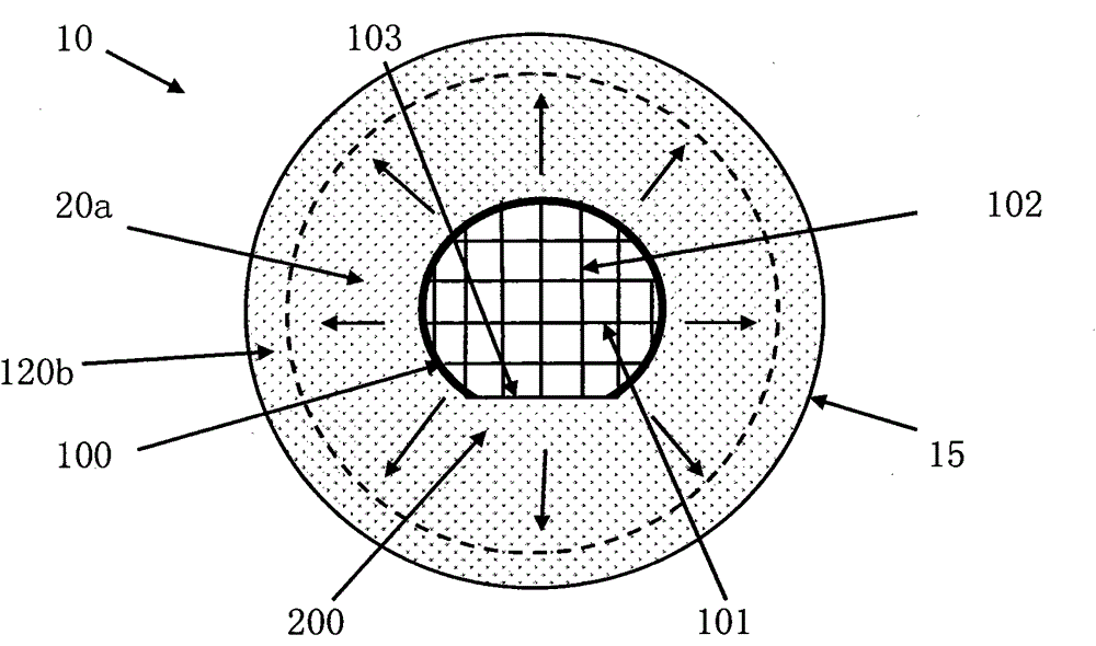
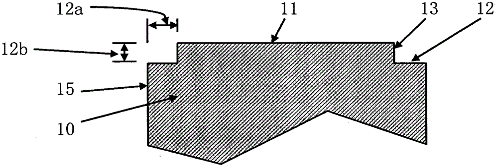
[0085] An implementation example: Figure 6a The display expander and Figure 1a The traditional crystal expander shown is similar: the difference is: Figure 6a The crystal expanding machine comprises the annex 60 ( Figure 6k and Figure 6n ). The blue membrane contact surface 63 on the top of the attachment 60 is on the same plane as the blue membrane contact surface 11 of the top membrane structure 10 . A through hole 62 a is formed in the center of the attachment 60 , and the diameter of the through hole 62 a matches the diameter of the top membrane structure 10 , so that the attachment 60 can be fixed on the top of the top membrane structure 10 .

[0086] An implementation example: Figure 6a The display expander and Figure 4a The expanders shown are similar: the differences are: (1) Figure 6a The periphery 15 of the crystal expansion ring supporting surface 12 can also be circular; (2) Figure 6a The expansion machine includes accessories 60 (such as Figure 6...


PUM


Abstract

The invention provides a wafer expander used in the semiconductor industry and the LED industry. A cross blue film is expanded in the direction of two mutually perpendicular chip cutting ways so that the cut wafers stuck to the cross blue film are evenly expanded and chips can be separated. The distances between the adjacent chips are the same, the subsequent measurement and sorting processes occupy less machine identification and positioning time, the requirements of chip-level packaging or wafer-level packaging are met, and the subsequent processes are facilitated.

Description

technical field [0001] The invention relates to a crystal expander used in the semiconductor industry and the LED industry, so that the wafers can be expanded evenly, the distance between adjacent chips is equal, the machine resolution and positioning time occupied by the subsequent measurement and sorting process can be reduced, and the wafer can be achieved. Level packaging requirements, to facilitate the subsequent process flow. Background technique [0002] The cutting streets of square and rectangular chips on the wafer are along two directions perpendicular to each other: the X direction and the Y direction, and the X direction is parallel to the flat side of the wafer. Existing wafer expanders expand along the radial direction of the wafer. Therefore, the distance between adjacent chips (chips) in the same dicing line direction is not equal, making the subsequent measurement and sorting process It takes up more time for machine resolution and positioning. In additio...

Claims


Application Information

Patent Timeline
Patent Type & Authority Applications(China)
IPC IPC(8): H01L21/67
CPCH01L21/67092
Inventor 彭晖
Owner FOSHAN CITY NANHAI DISTRICT LIANHE GUANGODNG XINGUANGYUAN IND INNOVATION CENT
Why Eureka
Try Eureka