Inner cavity polyurethane foam metal profile by threading method
A metal profile and foamed metal technology, which is applied to wing sash frames, windows/doors, building components, etc., can solve problems such as reduced thermal insulation, improve thermal insulation and structural strength, save equipment, and simplify processes. Effect
- Summary
- Abstract
- Description
- Claims
- Application Information
AI Technical Summary
Problems solved by technology
Method used
Image

Examples
specific Embodiment approach 1
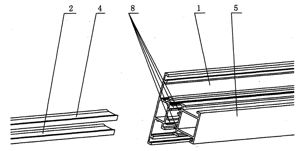
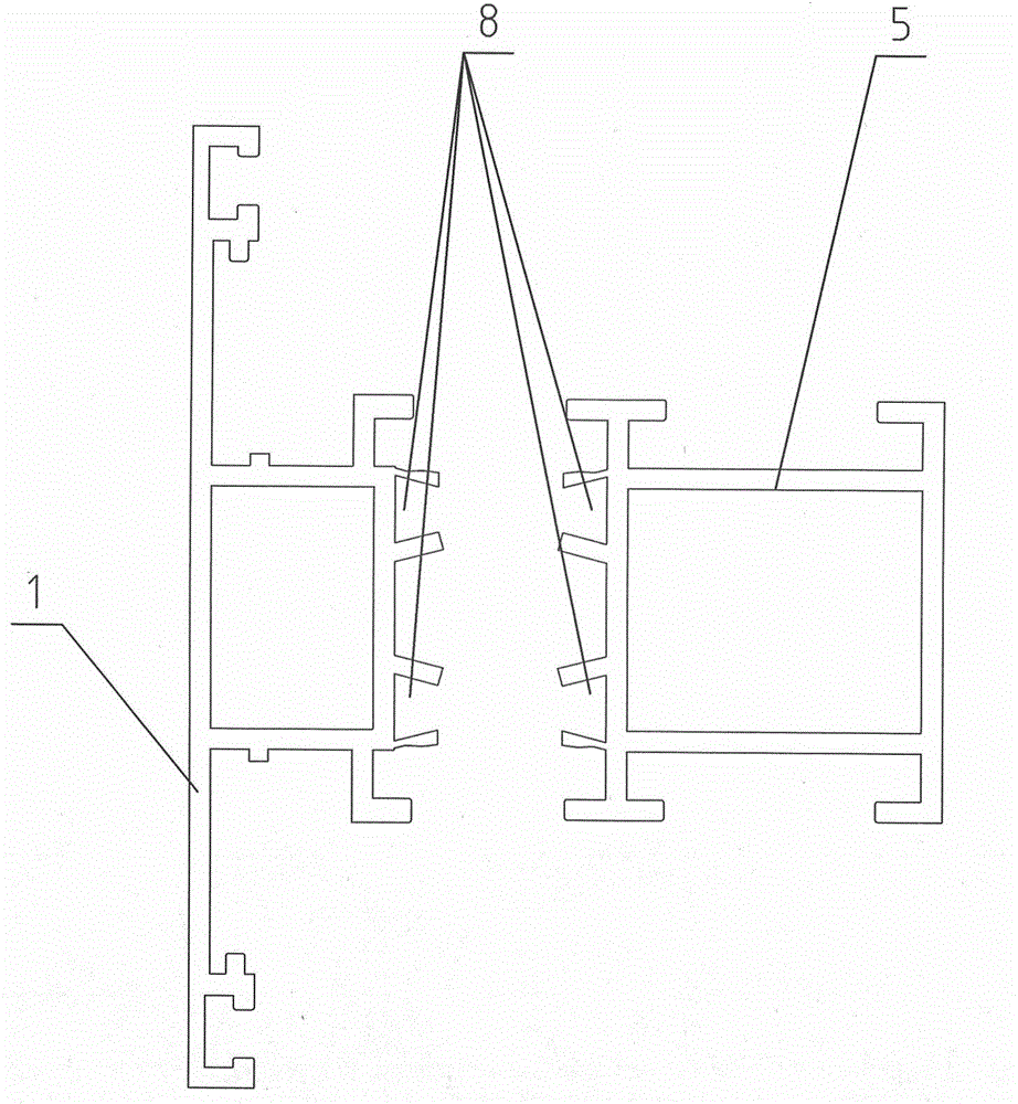
[0019] Specific implementation mode one: as Figure 1 to Figure 7 As shown, the inner-cavity polyurethane foam metal profile by threading method described in this embodiment is composed of metal profile A1, metal profile B5, threading strip A2, threading strip B4, and polyurethane foam strip 7. It is characterized in that both the metal profile A1 and the metal profile B5 have a dovetail notch 8, and both sides of the cross section of the threading strip A2 and the threading strip B4 have shapes corresponding to the dovetail notch 8, and the threading strip A2 and the threading strip B4 are respectively worn on In the dovetail notch 8 of metal profile A1 and metal profile B5, metal profile A1, metal profile B5, threading strip A2, and threading strip B4 are combined to form a cavity 13, and the cavity 13 is filled with polyurethane foam strip 7, and the metal profile A1, the metal profile B5 and the threaded strip A2, threaded B4, and polyurethane foam strip 7 have the same le...
specific Embodiment approach 2
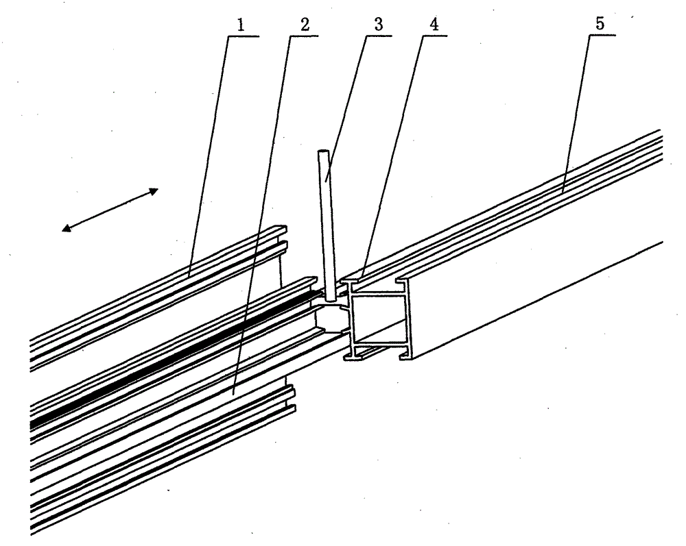
[0026] Specific implementation mode two: as Figure 1 to Figure 7 As shown in this embodiment, insert the threading strip A2 into the lower dovetail slot 8 of the metal profile A1, align the lengthwise direction of the threading strip A2 and the metal profile A1, and thread the threading strip B4 into the upper dovetail groove of the metal profile B5 In the port 8, align the length direction of the strip B4 and the metal profile B5, the right end of the metal profile A1 is located at the left end of the metal profile B5, the glue injection nozzle 3 is located at the left end of the metal profile B5, the metal profile A1 is fixed, and the glue injection nozzle 3 , The threading strip B4 and the metal profile B5 can move along the left and right directions, the polyurethane 6 is glued to the upper surface of the threading strip A2 through the glue injection nozzle 3 of the glue injection head, and at the same time, the threading strip B4 is penetrated into the upper dovetail groo...
specific Embodiment approach 3
[0027] Specific implementation mode three: as Figure 1 to Figure 7 As shown, in this embodiment, the two ends of the metal profile A1 and the metal profile B5 in the length direction are aligned, the distance between the metal profile A1 and the metal profile B5 is fixed according to the set position, and the threading strip A2 and the threading strip B4 are respectively inserted into the metal profile A1 , In the dovetail notch 8 of the metal profile B5, the two sides of the threading strip A2, the threading strip B4, the metal profile A1, and the metal profile B5 are aligned, and the clamping block A9 and the clamping block B10 are respectively located at the left and right ends of the metal profile A1. Clamp the metal profile A1 and the threading strip A2 and move to the left, the clamping block C11 and the clamping block D12 are respectively located at the left and right ends of the metal profile B5, and clamp the metal profile B5 and the threading strip B4, the metal prof...
PUM
 Abstract
Description
Claims
Application Information
 - Generate Ideas
- Intellectual Property
- Life Sciences
- Materials
- Tech Scout
- Unparalleled Data Quality
- Higher Quality Content
- 60% Fewer Hallucinations
Browse by: Latest US Patents, China's latest patents, Technical Efficacy Thesaurus, Application Domain, Technology Topic, Popular Technical Reports.
© 2025 PatSnap. All rights reserved.Legal|Privacy policy|Modern Slavery Act Transparency Statement|Sitemap|About US| Contact US: help@patsnap.com