
Grinding machine

A grinding machine and station technology, which is applied in the field of grinding machines, can solve the problems of reduced work efficiency and worker efficiency, and achieve the effects of improving work efficiency, reducing placement time and processing time

Inactive Publication Date: 2014-08-27
ZHANGJIAGANG TIANDA TOOLS
View PDF7 Cites 0 Cited by
  • Summary
  • Abstract
  • Description
  • Claims
  • Application Information

AI Technical Summary

Problems solved by technology

[0002] Commonly used grinding machines include a self-rotating suction cup and a grinding wheel set above the suction cup. There is an electromagnet under the suction cup. Then drive the suction cup to rotate, the grinding wheel above the suction cup goes down and processes the metal parts, because the grinding wheel corresponds to an area of ​​the suction cup, so when the suction cup rotates a circle, all the metal parts are processed, and the grinding wheel is lifted at this time, And cut off the power supply to make the electromagnet lose power, and then the worker removes the metal parts from the suction cup, puts the metal parts that need to be processed again, and proceeds to the next batch of processing. During this process, the workers only place the metal parts During the entire processing process, workers do not need to work, and it is a long process to wait for all the metal parts on the suction cup to be processed. During this long working process, the efficiency of workers is greatly reduced, thus lead to a decrease in overall work efficiency

Method used


Image

  • Grinding machine
  • Grinding machine

Examples


Embodiment Construction

[0013] Specific embodiments of the present invention will be described in detail below in conjunction with the accompanying drawings.

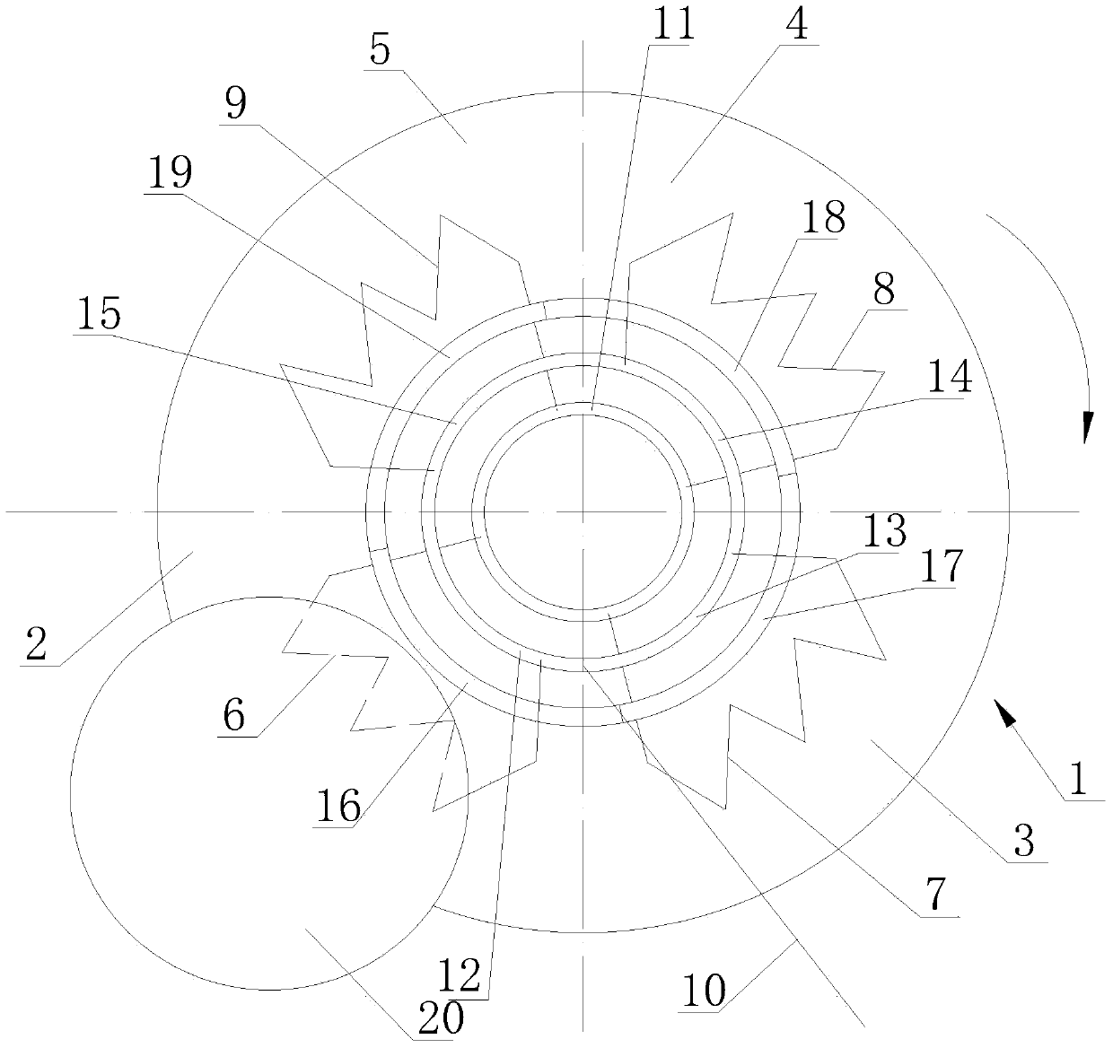
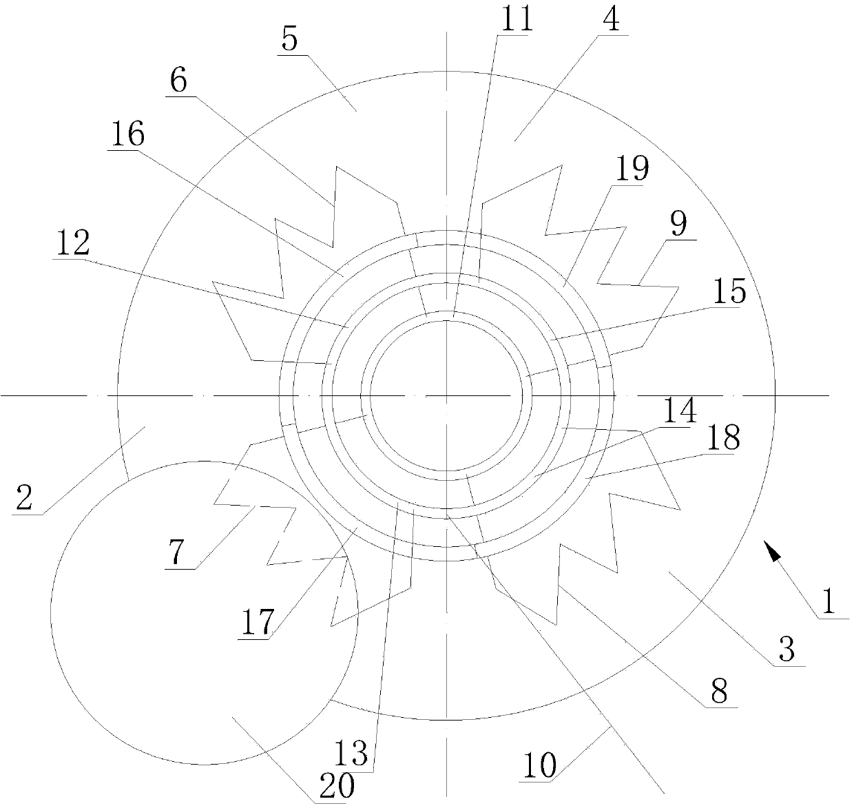
[0014] Such as figure 1 As shown, the grinding machine of the present invention includes a self-rotating suction cup 1 and a grinding wheel 20 arranged above the suction cup, and the suction cup is provided with a working station 2, a preliminary station 3 and at least one loading and unloading station. Two loading and unloading stations are adopted in the machine, that is, loading station 4 and unloading station 5. If the workers are skilled, the loading station and the unloading station can be placed on one station during actual production, that is, the workers are working The metal parts on position 2 can be removed from the loading and unloading station within the time after the processing is completed, and then put on the metal parts to be processed. All the stations are evenly distributed on the suction cup 1, that is, the working statio...


PUM


Abstract

The invention discloses a grinding machine which can greatly save the machining time of metal parts and can improve the working efficiency. The grinding machine comprises a sucking cup which can automatically rotate and a grinding wheel which is arranged above the sucking cup. The sucking cup is provided with a work station, a preparation station and at least one loading and unloading station. All the stations are evenly distributed on the sucking cup, and the grinding wheel is placed above the work station. An electromagnet is correspondingly arranged below each station, and the electromagnets on all the stations work independently. The electromagnet on the work station and the electromagnet on the preparation station are always electrified, and the electromagnet on the loading and unloading station is in outage. The grinding machine has the advantages that after the sucking cup is provided with the work station, the preparation station and the at least one loading and unloading station, the entire device can be kept in the working state all the time, namely shutdown can not happen, the overall placing time and machining time of the metal parts are reduced, and therefore the working efficiency is improved.

Description

technical field [0001] The present invention relates to a grinding machine. Background technique [0002] Commonly used grinding machines include a self-rotating suction cup and a grinding wheel set above the suction cup. There is an electromagnet under the suction cup. Then drive the suction cup to rotate, the grinding wheel above the suction cup goes down and processes the metal parts, because the grinding wheel corresponds to an area of ​​the suction cup, so when the suction cup rotates a circle, all the metal parts are processed, then lift the grinding wheel, And cut off the power supply to make the electromagnet lose power, the worker removes the metal parts from the suction cup, puts the metal parts to be processed again, and proceeds to the next batch of processing. During this process, the workers only place the metal parts During the entire processing process, workers do not need to work, and it is a long process to wait for all the metal parts on the suction cup t...

Claims


Application Information

Patent Timeline
Patent Type & Authority Applications(China)
IPC IPC(8): B24B41/06
CPCB24B41/06
Inventor 张理
Owner ZHANGJIAGANG TIANDA TOOLS
Learn More