Input adaptive self-excited sepic converter
An adaptive and self-excited technology, applied in the direction of converting DC power input to DC power output, output power conversion devices, instruments, etc., can solve the problems of weak limit protection ability, large freewheeling conduction loss, and large loss , to achieve the effects of fewer components, less rectification loss, and less current detection loss
- Summary
- Abstract
- Description
- Claims
- Application Information
AI Technical Summary
Problems solved by technology
Method used
Image

Examples
Embodiment 1
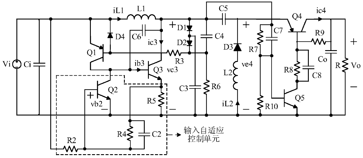
[0028] Such as figure 2 as shown,
[0029] An input adaptive self-excited Sepic converter, including an input circuit, a main circuit and an output circuit, the input circuit includes a DC voltage source Vi and an input capacitor Ci, the output circuit includes an output capacitor Co and a load R, and the main circuit includes an inductor L1 , PNP type BJT tube Q1, NPN type BJT tube Q3, resistor R3, resistor R6, diode D1, diode D2, capacitor C5, diode D3, inductor L2, diode D4, capacitor C3, capacitor C4 and capacitor C6. The main circuit also includes an input adaptive control unit and a freewheeling sub-circuit. The input adaptive control unit includes a resistor R2, a resistor R4, a resistor R5, a capacitor C2 and an NPN type BJT tube Q2. The freewheeling subcircuit is connected to the cathode of the diode D3 and Between the positive terminals of the DC output voltage Vo.
[0030] The input capacitor Ci is connected in parallel with the DC voltage source Vi, the voltage ...
Embodiment 2
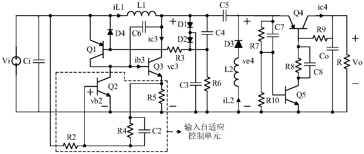
[0047] Such as image 3 , Figure 4 and Figure 5 As shown, on the basis of Embodiment 1, one end of capacitor C7 connected to the collector of NPN type BJT transistor Q3 and one end of R7 are changed to the emitter electrode of PNP type BJT transistor Q4, that is, one end of capacitor C7 and one end of R7 One end is connected to the emitter of the PNP type BJT transistor Q4, and the other end of C7 and the other end of R7 are connected to the base of the NPN type BJT transistor Q5. Other structures and working process of embodiment 2 are the same as embodiment 1.
Embodiment 3
[0049] Such as Figure 6 As shown, on the basis of Embodiment 1, a blanking time control branch composed of resistor R1 and capacitor C1 is added. One end of resistor R1 is connected to the collector of NPN type BJT transistor Q3, and the other end of resistor R1 is connected to capacitor C1 One end of the capacitor C1 is connected to the other end of the capacitor C1 and the base of the NPN BJT transistor Q2 is connected. The blanking time control branch has a correction effect on the input adaptive control unit, and can achieve the effect of widening the working range of the circuit.
[0050] Embodiment 3 In the steady state, the voltage simulation working waveform diagram of the inductor current iL1 is critically continuous and the inductor current iL2 is intermittent. Figure 7 As shown, the current simulation working waveform diagram of the inductive current iL1 in the steady state of embodiment 3 is critically continuous and the inductive current iL2 in the discontinuou...
PUM
 Abstract
Description
Claims
Application Information
 - Generate Ideas
- Intellectual Property
- Life Sciences
- Materials
- Tech Scout
- Unparalleled Data Quality
- Higher Quality Content
- 60% Fewer Hallucinations
Browse by: Latest US Patents, China's latest patents, Technical Efficacy Thesaurus, Application Domain, Technology Topic, Popular Technical Reports.
© 2025 PatSnap. All rights reserved.Legal|Privacy policy|Modern Slavery Act Transparency Statement|Sitemap|About US| Contact US: help@patsnap.com