Solar cell and module group thereof

A technology for solar cells and back electrodes, applied in circuits, photovoltaic power generation, electrical components, etc., can solve the problems of high Redge, affect the conversion efficiency of the battery, and decrease the fill factor, so as to improve the current collection effect, improve the photoelectric conversion efficiency, and improve the The effect of conductive contact area

Inactive Publication Date: 2014-08-13
MOTECH INDUSTRIES
View PDF5 Cites 4 Cited by
  • Summary
  • Abstract
  • Description
  • Claims
  • Application Information

AI Technical Summary

Problems solved by technology

[0004] The area where the back electrode 95 of the PERC battery contacts the back surface 912 of the substrate 91 is equivalent to the area of ​​the plurality of openings 941 of the passivation layer 94. Due to the limited area of ​​the plurality of openings 941, the back electrode 95 The area in contact with the back surface 912 is less, thus causing the series resistance (Rs) of the battery to be too large, and the current collection effect is not good
Moreover, according to the journal IEEE JOURNAL OF PHOTOVOLTAICS, VOL.1, NO.1, JULY2011, "Evaluation of Series Resistance Losses in Screen-Printed Solar Cells With Local Rear Contacts", the four corners 913 of the back side 912 of the battery are more likely to occur The problem of high impedance, that is, the high Redge mentioned in the journal, and the smaller the area where the back electrode 95 contacts the back surface 912 through the plurality of openings 941, the more significant the above-mentioned high Redge phenomenon, which will lead to filling Factor (Fill Factor) decreases and affects the conversion efficiency of the cell, so known PERC solar cells need to be improved

Method used


Image

  • Solar cell and module group thereof
  • Solar cell and module group thereof
  • Solar cell and module group thereof

Examples


Embodiment Construction

[0036] The present invention will be described in detail below with reference to the accompanying drawings and embodiments. It should be noted that in the following description, similar elements are denoted by the same numerals.

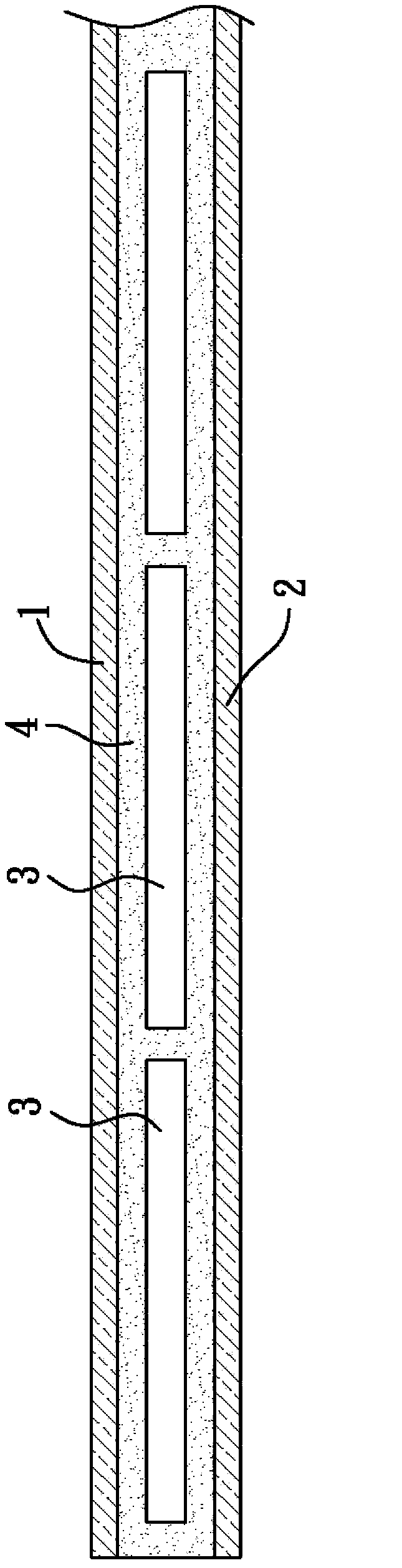
[0037] refer to image 3 , Figure 4 , Figure 5 The first preferred embodiment of the solar cell module of the present invention includes: a first plate 1 and a second plate 2 arranged up and down oppositely, and a plurality of arrays are arranged between the first plate 1 and the second plate 2 The solar cells 3 and at least one encapsulation material 4 located between the first plate 1 and the second plate 2 and wrapped around the plurality of solar cells 3 .

[0038] The implementation of the first plate 1 and the second plate 2 is not particularly limited, glass or plastic plates can be used, and the plate on the side of the light-receiving surface of the battery must be light-transmissive. The material of the packaging material 4 is, for exa...


PUM


Abstract

A solar cell and a module group thereof are disclosed. The cell comprises a substrate having a light receiving face and a back face that are opposite to each other, a passivation layer which is arranged on the back face and is provided with an opening part, and a back face electrode which is positioned on the passivation layer and contacts with the back face through the opening part, wherein the opening part is provided with a first opening pattern and a second opening pattern, wherein the first opening pattern extends along the circumferential edge of the substrate and is annular in shape, the second opening pattern is surrounded by the first opening pattern and is provided with a plurality of sub-openings, and distance between the first opening pattern and the circumferential edge of the substrate is smaller than 5 mm. The first opening pattern is arranged at the outer periphery of the second opening pattern, the first opening pattern is arranged close to the circumferential edge of the substrate, an electric conduction area between the back face electrode and the substrate can be improved, and thus electric current collection effects and photoelectric conversion efficiency can be improved.

Description

technical field [0001] The invention relates to a solar cell and its module, in particular to a silicon crystal solar cell and its module. Background technique [0002] refer to figure 1 , figure 2 , the known silicon solar cell mainly includes: a substrate 91 with an opposite light-receiving surface 911 and a back surface 912, a front electrode 92 on the light-receiving surface 911, a plurality of local back surface electric fields on the back surface 912 (Local Back Surface Field, LBSF for short) 93, a passivation layer 94 located on the back surface 912 and having a plurality of openings 941, and a passivation layer 94 located on the passivation layer 94 and capable of contacting the back surface 912 through the plurality of openings 941 back electrode 95 . [0003] The passivation layer 94 is used to fill and reduce surface defects of the substrate 91 , thereby reducing the recombination rate of carriers at the back surface 912 of the substrate 91 , so as to improve ...

Claims


Application Information

Patent Timeline
Patent Type & Authority Applications(China)
IPC IPC(8): H01L31/0216H01L31/0224H01L31/068H01L31/042
CPCY02E10/50H01L31/02167H01L31/022441H01L31/042H01L31/068Y02E10/547
Inventor 刘浩伟赖俊文
Owner MOTECH INDUSTRIES
Why Eureka
Try Eureka