
Rail-to-rail differential input circuit

A differential input circuit, differential pair technology, applied in differential amplifiers, improved amplifiers to reduce temperature/power supply voltage changes, DC-coupled DC amplifiers, etc. The effect of small current variation, reducing variation and improving load capacity

Inactive Publication Date: 2014-08-06
SHANGHAI HUALI MICROELECTRONICS CORP
View PDF5 Cites 14 Cited by
  • Summary
  • Abstract
  • Description
  • Claims
  • Application Information

AI Technical Summary

Problems solved by technology

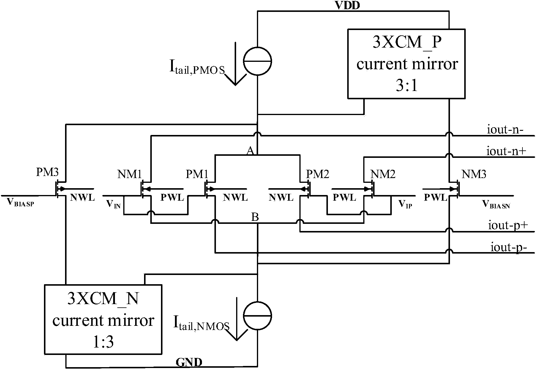
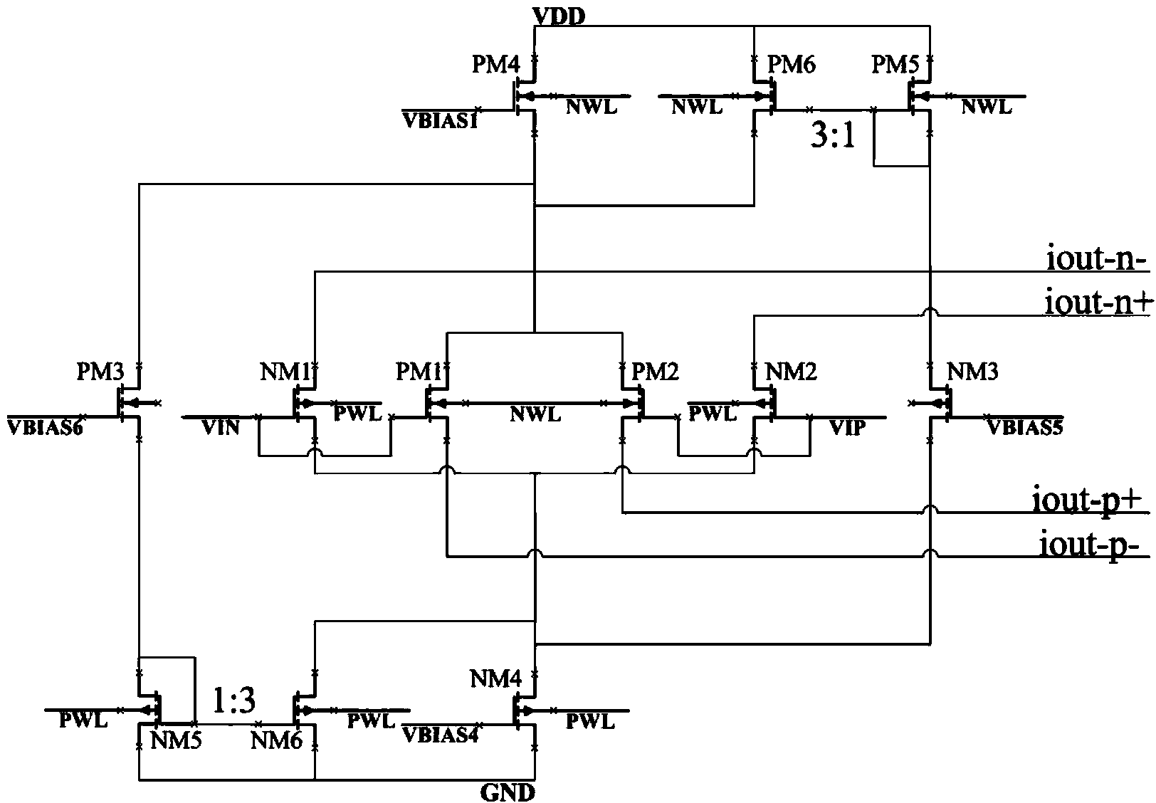
Since the current of PM4 or NM4 is the tail current of the differential input pair, its square root value is proportional to the transconductance of the transistor of the differential input pair, therefore, the change of the current source current will cause a large change in the transconductance of the input stage at full voltage
In addition, in the 3x current mirror modules 3XCM_N and 3XCM_P, the output current of this basic current mirror structure will also change greatly with the change of the drain voltage of the output tube, which reduces the accuracy of the current mirror

Method used


Image

  • Rail-to-rail differential input circuit
  • Rail-to-rail differential input circuit
  • Rail-to-rail differential input circuit

Examples


Embodiment Construction

[0042] In order to make the content of the present invention clearer and easier to understand, the content of the present invention will be further described below in conjunction with the accompanying drawings. Of course, the present invention is not limited to this specific embodiment, and general replacements known to those skilled in the art are also covered within the protection scope of the present invention.

[0043] In this specification and in the claims, it will be understood that when an element is referred to as being "connected to" or "connected to" another element, it can be directly connected to the other element or intervening elements may be present. .

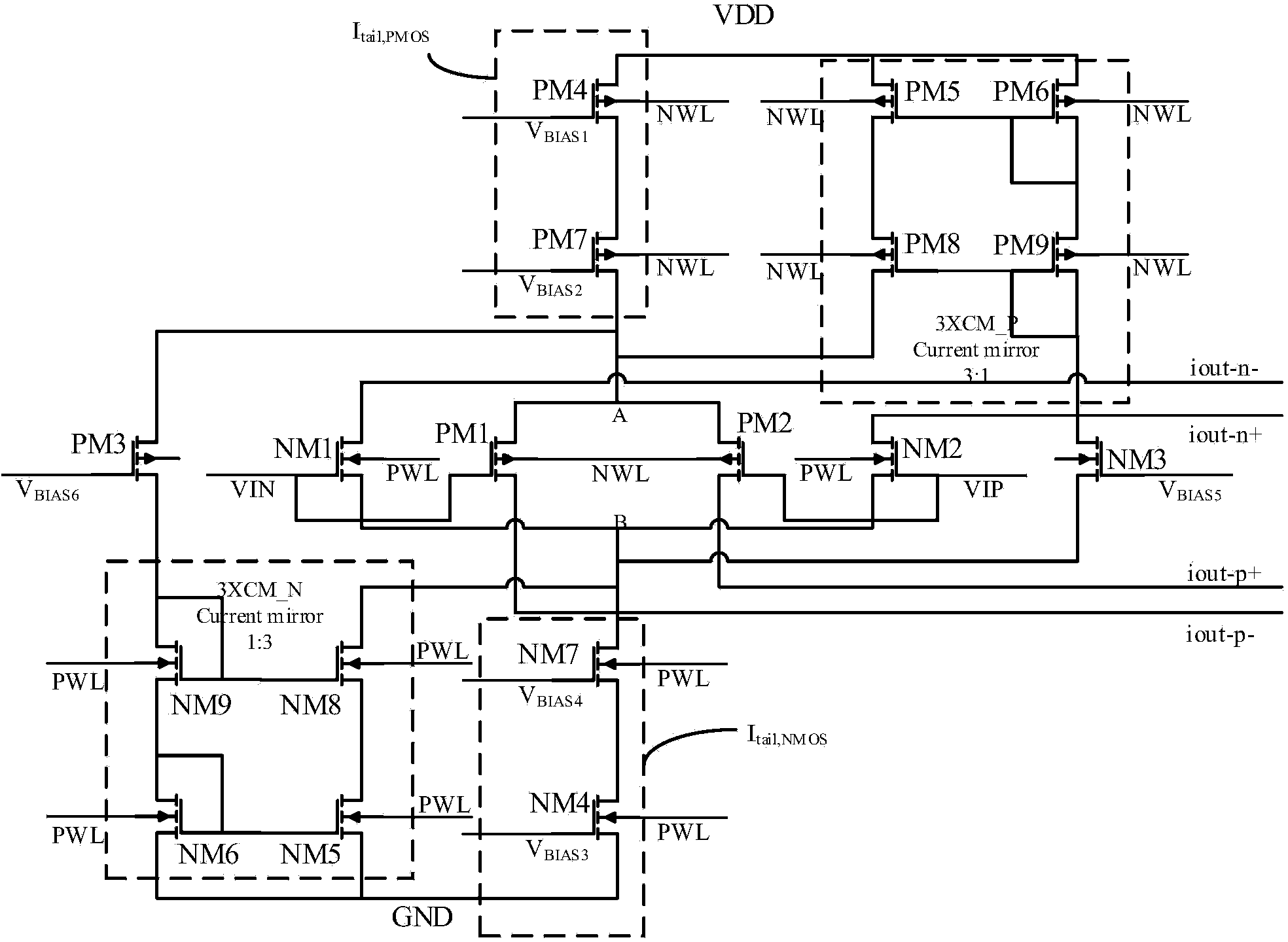
[0044] image 3 It is a schematic circuit diagram of a rail-to-rail differential input circuit according to an embodiment of the present invention. The rail-to-rail differential input circuit can be used as an input stage of an operational amplifier, such as a rail-to-rail operational amplifier applied in a 55...


PUM


Abstract

The invention discloses a rail-to-rail differential input circuit which comprises a PMOS differential pair, an NMOS differential pair, a PMOS switch tube, an NMOS switch tube, a PMOS current source, an NMOS current source, a PMOS current mirror and an NMOS current mirror. The currents output by the PMOS current source and the NMOS current source are equal, and the PMOS current source comprises a first PMOS transistor and a second PMOS transistor, wherein the first PMOS transistor and the second PMOS transistor form a cascade structure. The NMOS current source comprises a first NMOS transistor and a second NMOS transistor, wherein the first NMOS transistor and the second NMOS transistor form a cascade structure. According to the rail-to-rail differential input circuit, the tail current precision can be improved, and the better constant transconductance effect can be achieved.

Description

technical field [0001] The present invention relates to operational amplifiers, and more particularly to rail-to-rail differential input stage circuits in operational amplifier circuits. Background technique [0002] In the rail-to-rail operational amplifier (Rail-to-Rail OPAMP) design, the input stage is required to have a constant transconductance function (constant transconductance) from the low potential of the power supply to the high potential, that is, within the rail-to-rail voltage range ). However, a single PMOS or NMOS differential input pair will be in the cut-off, sub-threshold, linear and saturated four operating regions in the full voltage range, and its transconductance can vary from zero to maximum. [0003] Because the PMOS differential pair is in the saturation region at low voltage and in the cutoff region at high voltage; while the NMOS differential pair is just the opposite, it is in the saturation region at high voltage and in the cutoff region at low...

Claims


Application Information

Patent Timeline
Patent Type & Authority Applications(China)
IPC IPC(8): H03F3/45H03F1/30
Inventor 谢加雄张宁马腾飞
Owner SHANGHAI HUALI MICROELECTRONICS CORP
Learn More