Anti-blocking grouting nozzle

An anti-clogging and sprinkler technology, applied in construction, infrastructure engineering and other directions, can solve the problems of project progress and quality impact, grouting pipe clogging accident, unsatisfactory effect and other problems, and achieve good construction quality, good anti-clogging performance and high efficiency. Effect

Inactive Publication Date: 2014-08-06
SHENYANG AGRI UNIV
View PDF10 Cites 1 Cited by
  • Summary
  • Abstract
  • Description
  • Claims
  • Application Information

AI Technical Summary

Problems solved by technology

[0003] During the high-spray grouting operation, the grouting pipe is inserted into the grouting hole that is always filled with mud, and the pressure of the cement slurry and low-pressure air delivered to the grouting pipe by the high-pressure mud pump and air compressor is far greater than the static pressure of the mud liquid column outside the grouting pipe. However, during normal shutdown, disconnection of the grouting pipe, or bursting of the grouting or air hose, the internal and external pressure of the grouting nozzle quickly and automatically balances, but the pressure of the gas pipeline in the grouting pipe suddenly drops to zero. Under the strong static pressure of the mud, the mud and sand outside the pipe are instantly crowded into the annular air nozzle, which causes the clogging accident of the grouting pipe, which has a significant impact on the progress and quality of the project. For this reason, many domestic and foreign counterparts have adopted many measures to prevent nozzle clogging measures, but the effect is not ideal

Method used


Image

  • Anti-blocking grouting nozzle
  • Anti-blocking grouting nozzle
  • Anti-blocking grouting nozzle

Examples


Embodiment Construction

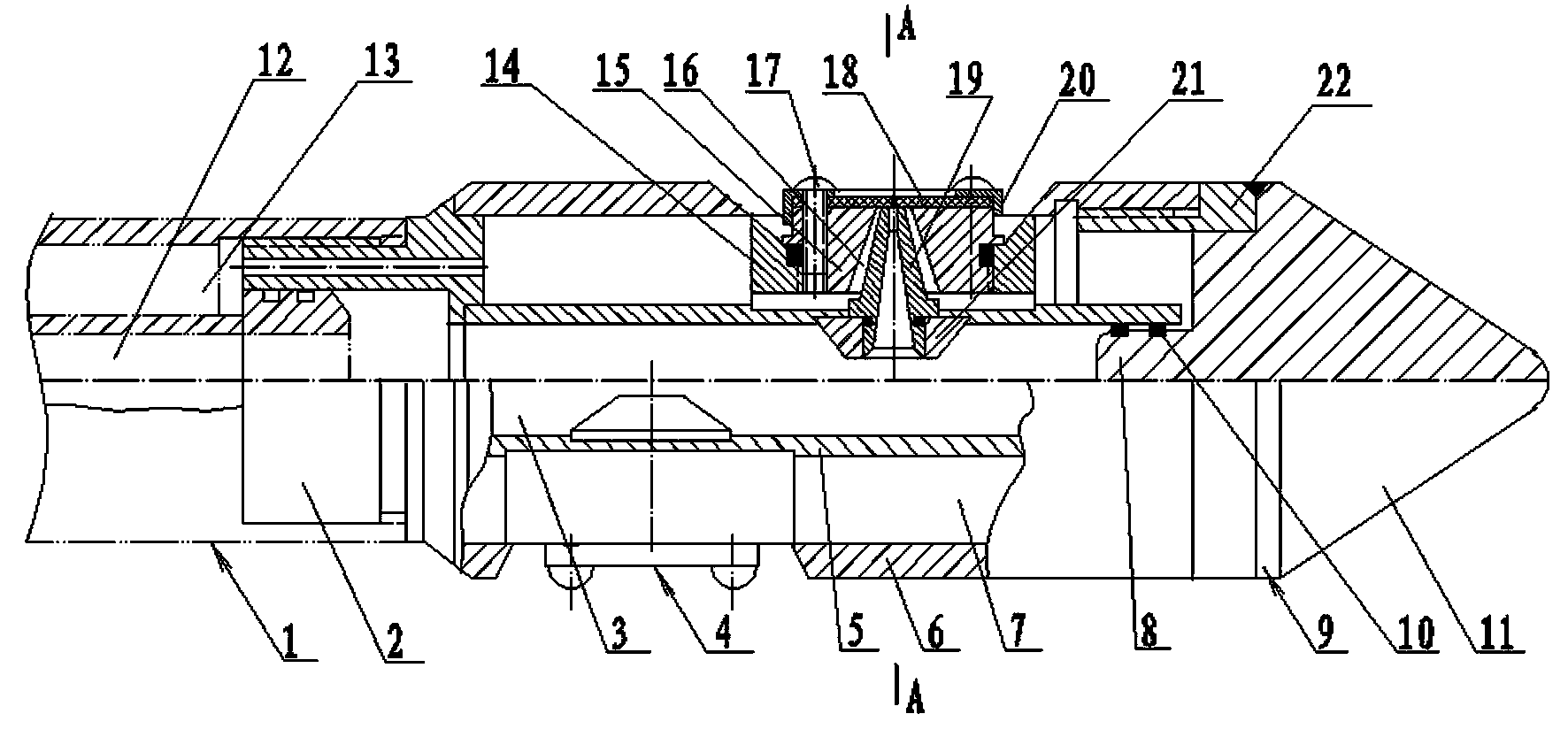
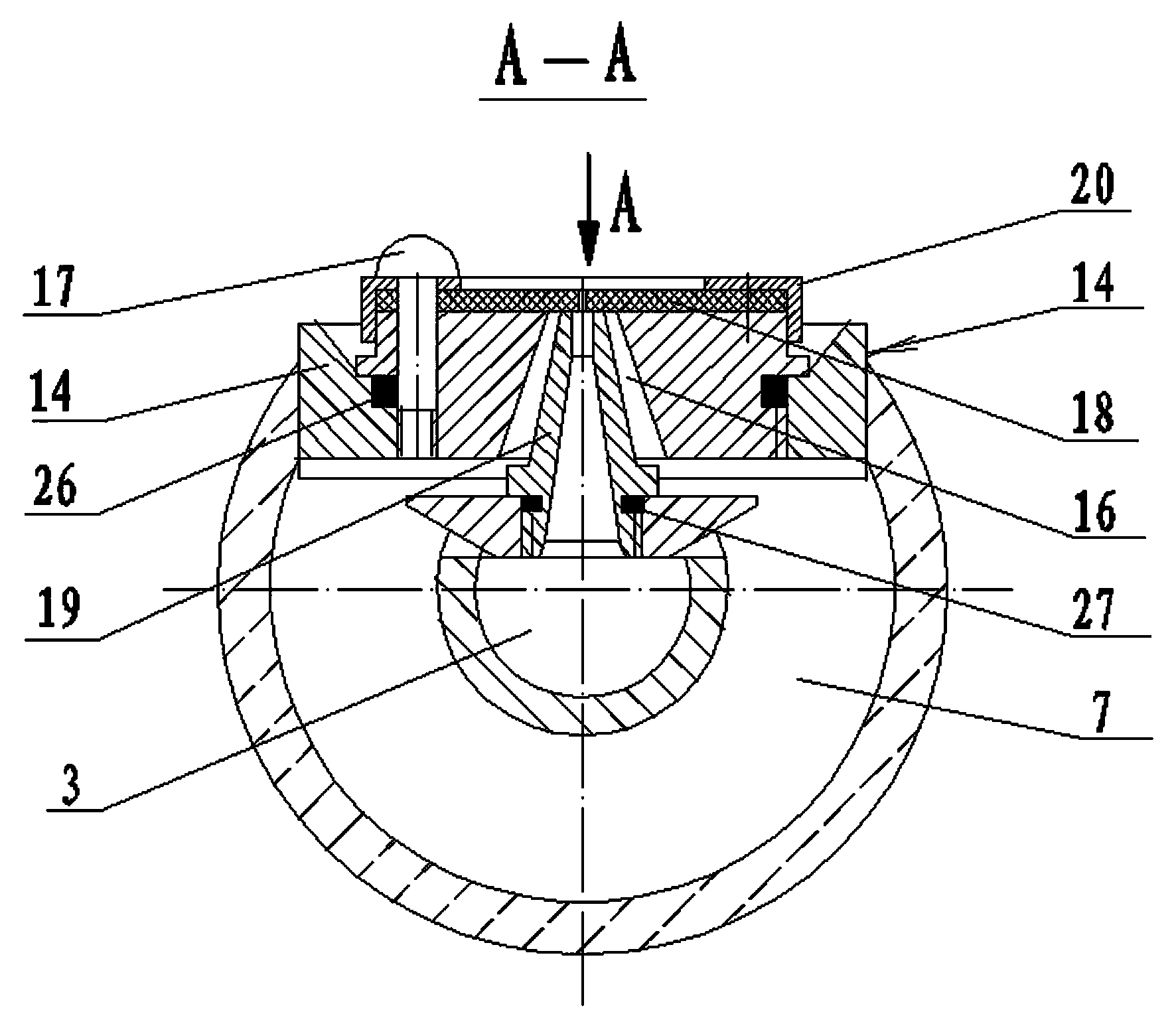
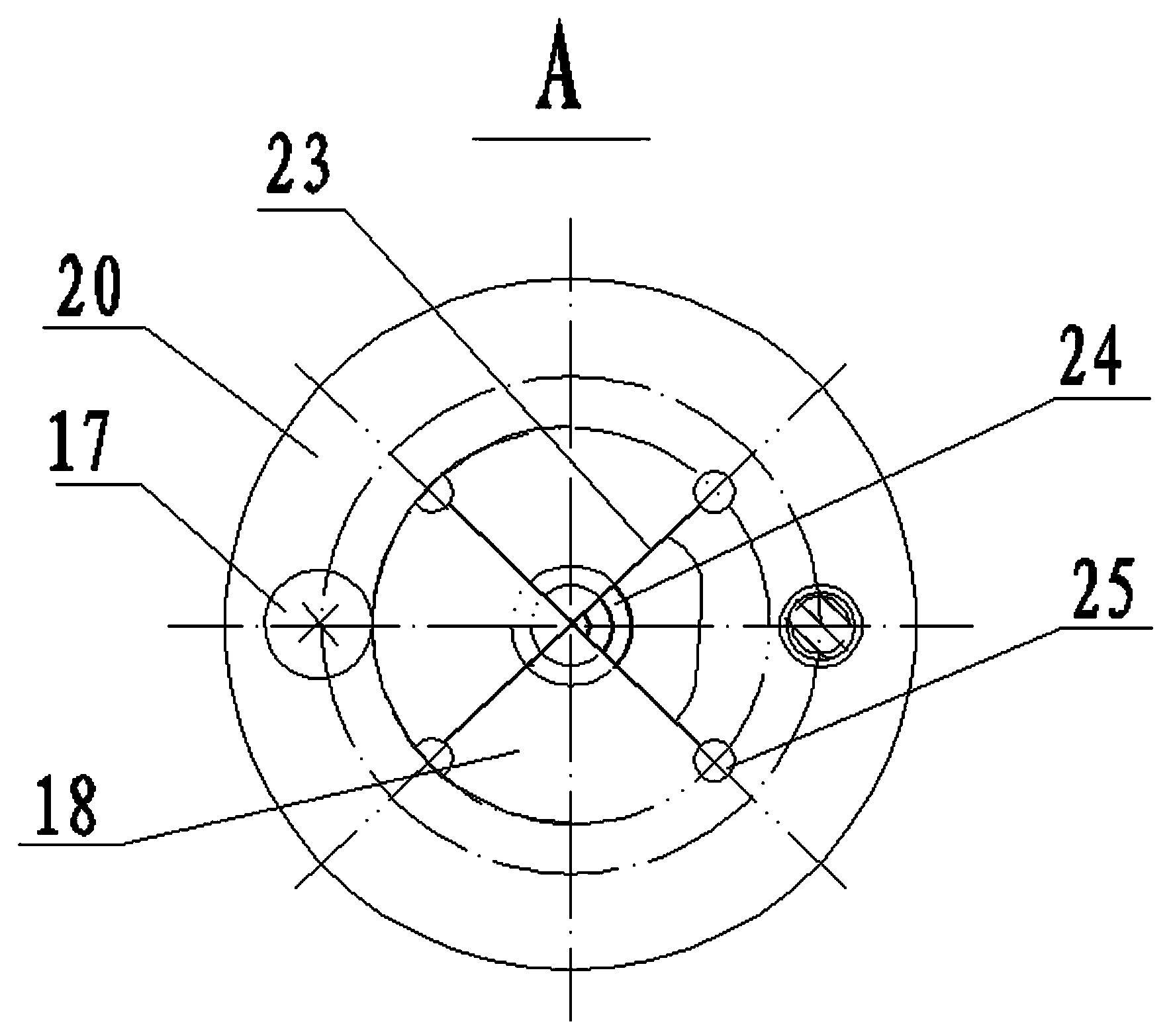
[0012] The anti-clogging grouting nozzle includes a nozzle assembly 4, an inner pipe 5, an outer pipe 6, a cone head 9, and a handle 2. The handle 2 is connected to the grouting pipe 1 through an external thread at one end, and the other end is welded with the inner pipe 5 and the outer pipe 6 of the same longitudinal axis. The air passage 13 communicates with the annular air passage 7 between the inner and outer pipes. The cone head 9 is welded by a cone body 11 with a mandrel 8 at one end and a 60° cone at the other end and a threaded sleeve 22. Seal with the mandrel sealing ring 10. The nozzle assembly 4 is composed of a nozzle 19 , a nozzle seat 21 , an air nozzle 15 , an air nozzle seat 14 , a valve 18 and a gland 20 . The nozzle 19 is an injection nozzle with a tapered passage inside. The nozzle 19 is connected with the nozzle seat 21 by coaxial threads and sealed with the nozzle sealing ring 27. The interior of the gas nozzle 15 matches the tapered outer circle of the...


PUM


Abstract

An anti-blocking grouting nozzle comprises a spray nozzle assembly, an inner tube, an outer tube, a conical head and a connector, one end of the connector is in threaded connection with a grouting pipe, the other end of the connector is welded to an inner pipe and the outer pipe, and the grout channel of the grouting pipe, the grout channel of the inner pipe and air channel of the grouting pipe are respectively made to be communicated with the air channel between the inner pipe and the outer pipe. The conical head is in threaded connection with the outer tube through a thread busing and is connected with the inner pipe in a sleeved mode at the same time. A conical channel is arranged in a grout nozzle of the spray nozzle assembly, and the grout nozzle is in threaded connection with a grout nozzle seat, a conical hole matched with the conical channel of the grout nozzle is formed in an air nozzle, the air nozzle is mounted on the grout nozzle in a sleeved mode, and the air nozzle is in threaded connection with an air nozzle seat. The grout nozzle seat and the air nozzle seat are welded to the inner pipe and the outer pipe respectively. An arranged valve is a circular rubber sheet of identical outer diameter with the air nozzle, the center of the circular rubber sheet is cut into four parts, and the circular rubber sheet is fixed to the upper surface of the air nozzle and covers an annular air jet hole in the same plane with the grout nozzle. A great amount of engineering practice shows that the nozzle is good in anti-blocking performance, safe, reliable, good in construction quality and high in efficiency.

Description

technical field [0001] The invention relates to mechanical equipment for geotechnical engineering foundation treatment, in particular to an anti-clogging grouting nozzle for high-pressure jet grouting. Background technique [0002] In recent years, in building foundation treatment engineering, the two-pipe high-pressure jet grouting method has been widely used because of its unique functions and good effects. Small-diameter grouting holes, and then place the grouting pipe and the grouting nozzle at the bottom of the ground at the designed depth through the grouting hole, and input low-pressure air and ultra-high-pressure cement slurry into the grouting pipe and the coaxial steel pipe on the ground, and ultra-high-pressure The cement slurry and the low-pressure air are sprayed by the grout nozzle and the coaxial annular air nozzle respectively, and the high-pressure horizontal jet punches and stirs the stratum to form piles or walls deep underground. [0003] During the high...

Claims


Application Information

Patent Timeline
Patent Type & Authority Applications(China)
IPC IPC(8): E02D15/02
Inventor 张静
Owner SHENYANG AGRI UNIV
Why Eureka
Try Eureka