


Quick Research
Generate reliable direction feasibility study reports for your R&D in just a few steps.

Technical Q&A
Discover and master advanced knowledge NOW. Basics, ideas, possibilities, all at once.

Find Solutions
As an expert in R&D theories, this can generate solutions to your technical problems instantly.

Evaluate Feasibility
Analyze your overall solution with one click, know your potential R&D risks in advance.

Monitor Landscape
Get weekly tech updates, stay abreast of the latest tech innovations and key insights.
Embedded water storage tank for energy-saving toilet and bath room
A technology for water storage tanks and tanks, which is applied in the field of water gathering or water distribution devices and water intake. It can solve the problems of waste, restricted space for water storage tanks, and small water storage space, so as to save space, save water, and facilitate disassembly. The effect of pretending
- Summary
- Abstract
- Description
- Claims
- Application Information
AI Technical Summary
Problems solved by technology
Method used
Image

Examples
Embodiment 1
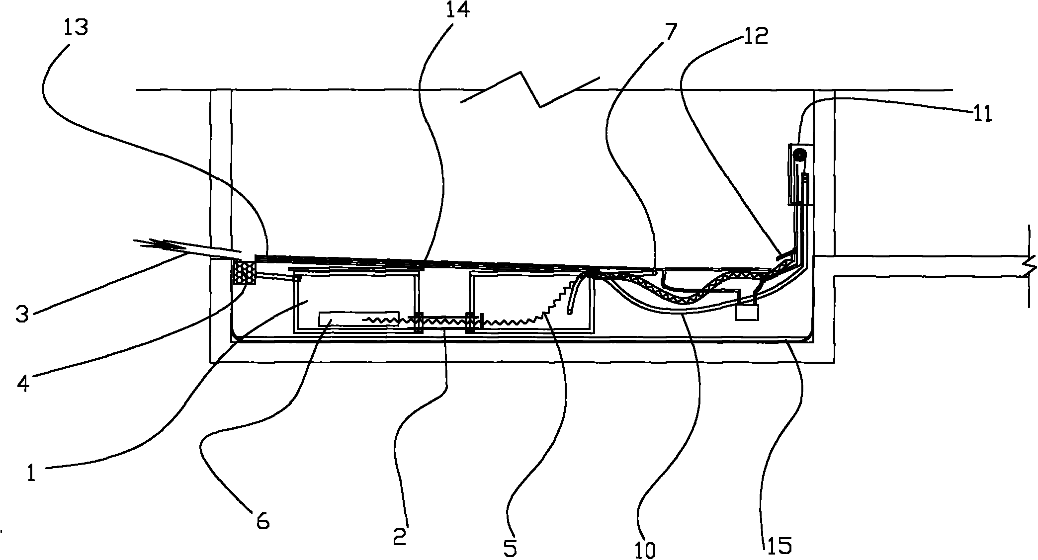
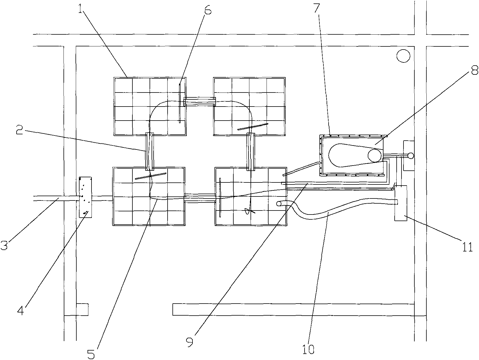
[0024] Such as figure 1 Shown is the structural representation of the energy-saving toilet bath buried water storage tank of the present invention; figure 2 Shown is the plan layout of the energy-saving toilet bath buried water storage tank of the present invention, the energy-saving toilet bath buried water storage tank of the present invention includes a box body 1, and the box body 1 is provided with a water inlet and a water outlet, and the box body 1 It is arranged between the waterproof protective layer 15 and the floor panel in the toilet, and an isolation layer and a mortar layer are arranged in sequence above the box body 1. Preferably, there are no less than two boxes, and the box body 1 Connecting pipes 2 are arranged in sequence.
[0025] In this embodiment, one or more water storage tanks are installed in the vacant space after the toilet 8 is installed, and the tanks are connected in sequence. Stone, concrete or mortar, and then lay a mortar layer on the isola...
Embodiment 2
[0032] The difference between this embodiment and Embodiment 1 is that it includes a box body, on which a water inlet and a water suction port are arranged, and the box body is arranged between the waterproof protective layer and the floor panel in the toilet, and the box body There is a box cover used as the ground surface layer on the top. In this embodiment, the box cover can be made to have a load-bearing capacity and a good appearance. The box cover can be directly used as the ground of the toilet bath, and a water stop is provided between the top cover and the box body. The sealing gasket connects the top cover and the box body through bolts. When veneering bricks, leave a seam around the box to facilitate the removal of the box cover.
PUM
 Abstract
Description
Claims
Application Information
 - R&D Engineer
- R&D Manager
- IP Professional
- Industry Leading Data Capabilities
- Powerful AI technology
- Patent DNA Extraction
Browse by: Latest US Patents, China's latest patents, Technical Efficacy Thesaurus, Application Domain, Technology Topic, Popular Technical Reports.
© 2024 PatSnap. All rights reserved.Legal|Privacy policy|Modern Slavery Act Transparency Statement|Sitemap|About US| Contact US: help@patsnap.com