Drive advancing train

A technology of trains and mine roads, which is applied in the field of mine road trains, which can solve the problems of damage to equipment and personnel, potential safety hazards, easy fall and injury, etc., and achieve the effects of improving efficiency, convenient transportation and assembly, and easy operation and maintenance

Active Publication Date: 2014-07-30
EJIN HORO BANNER WANQI MACHINING CO LTD
View PDF6 Cites 5 Cited by
  • Summary
  • Abstract
  • Description
  • Claims
  • Application Information

AI Technical Summary

Problems solved by technology

[0002] The removal and installation of the monorail ceiling beam requires cumbersome procedures, and the construction quality of the anchor rod for hanging the monorail crane fails due to the impact of mining on the working face and other reasons, and it is easy to fall and hurt people, posing a great safety hazard
[0003] The hard connection between the car and the car is corroded and aged in a humid environment for a long time, and the hard connection between the car and the car is prone to disconnection during the running time under complex conditions underground, and it is easy to cause a sports car accident, causing damage to equipment and casualties, and there are also large and Security risks
[0004] Equipment When the train is running, the train is pulled and released by winches, and one winch is installed at each end of the train. When the two winches are pulled and released inconsistently or the wire rope head falls off when the train is moving, a sports car accident occurs under complex conditions underground, and there are also major safety hazards.
[0005] The placement and retraction of the track in the original roadway requires at least six people to complete the installation of the track. During the work process, multiple people are required to cooperate with the operation, and it is easy to hurt others by misoperation, posing a safety hazard

Method used


Image

  • Drive advancing train
  • Drive advancing train
  • Drive advancing train

Examples


Embodiment 1

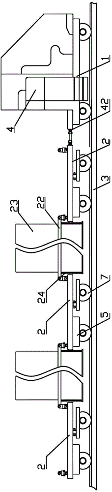
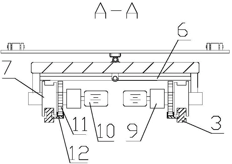
[0030] Embodiment 1: as figure 1 As shown, the train traveling in the mine road includes a train head 1 and three train chassis 2, the train head 1 and the adjacent train chassis 2 are connected by universal joints, and travel along the track 3, and a control system is provided in the train head 1. Switch 4; as in figure 2 As shown, a traveling wheel fixing plate 5 is fixedly arranged on both sides of the bottom of one end of each train chassis 2, and a traveling wheel regulating arm 6 is movably hinged at the bottom center of the other end, and a traveling wheel regulating arm 6 is fixedly provided at both ends of the advancing wheel regulating arm 6. Wheel fixed plate 5, is provided with traveling wheel 7 and traveling wheel driver 8 on each traveling wheel fixed plate 5, and traveling wheel driver 8 comprises reducer 9 and explosion-proof motor 10, and traveling wheel 7 is connected with explosion-proof motor 10 by reducer 9 , the traveling wheel 7 is driven by the explos...

Embodiment 2

[0031] Embodiment 2: as Figure 8 As shown, the mine road train includes a train head 1 and three train chassis 2, the train head 1 and the adjacent train chassis 2 are connected by universal joints, and travel along the track 3, and a control system is provided in the train head 1. Switch 4; Its overall structure is identical with embodiment 1, and difference is that it also comprises track installation vehicle 25, and track installation vehicle 25 comprises track installation chassis 28, is provided with track installation crane 29 on track installation chassis 28, and track installation The chassis 28 is connected to the front end of the train locomotive 1 through a cardan shaft; the traveling wheel drive 8 includes a pump station 26 and a hydraulic motor 27. Switch 4 is connected as Figure 9 As shown, the travel wheel 7 is driven by a hydraulic motor 27 .

Embodiment 3

[0032] Embodiment 3: as Figure 10 As shown, the mine road train includes a train locomotive 1, three train chassis 2, and a rail installation car 25. Its overall structure is the same as that of Embodiment 2, except that it also includes a rail row storage car 30 and a cable support car 31, such as Figure 11 As shown, the rail storage car 30 includes a track retractable chassis 32 and a bridge frame 33, a bridge lifting column 34 is arranged on the track retractable chassis 32, and a cable tray 35 is arranged on the top of the bridge lifting column 34, and one end of the cable tray 35 passes through the ten thousand The joint is hinged with one end of the bridge frame 33; the other end of the bridge frame 33 is connected with the self-moving tail of the belt conveyor through a universal joint, or connected with the self-moving tail of the scraper machine through a universal joint, or connected with the self-moving tail at the end of the roadway. The hydraulic support is con...


PUM


Abstract

The invention discloses a drive advancing train, comprising a train locomotive and train chassises; the train locomotive and the adjacent chassis are connected by a universal joint; a universal connection beam and a horizontal connection beam are arranged at the front and rear ends of each train chassis; each universal connection beam is horizontally arranged above one end of the corresponding train chassis; each horizontal connection beam is horizontal arranged above the other end of the corresponding train chassis; each two adjacent train chassises are connected by two parallelly-arranged connection arms; the corresponding ends of each two connection arms are respectively movably hinged to two ends of the universal connection beam of one train chassis; the other ends of each two connection arms are respectively movably hinged to the two ends of the horizontal connection beam of the other train chassis; mining equipment is suspended between each two connection arms. The drive advancing train has the advantages that the transportation and assembly are convenient, operation and maintenance are easy, and the suitability under the underground complex environment is strong. The efficiency of combined mining crossheading mobile substation train combined equipment and the moving efficiency of a cable liquid pipe are improved, the coal mining work efficiency is improved, and the cost is reduced.

Description

Technical field: [0001] The invention relates to a mine equipment, in particular to a mine road traveling train. Background technique: [0002] The removal and installation of the monorail ceiling beam requires cumbersome procedures, and the construction quality of the anchor bolts for hanging the monorail crane fails due to factors such as the impact of mining on the working face, and it is easy to fall and hurt people, posing a great safety hazard. [0003] The hard connection between the car and the car is corroded and aged in a humid environment for a long time, and the hard connection between the car and the car is prone to disconnection during the running time under complex conditions underground, and it is easy to cause a sports car accident, causing damage to equipment and casualties, and there are also large and Security risks. [0004] When the equipment train is running, the train is pulled and released by winches, and one winch is installed at each end of the tr...

Claims


Application Information

Patent Timeline
IPC IPC(8): B61D15/00
Inventor 赵云飞
Owner EJIN HORO BANNER WANQI MACHINING CO LTD
Why Eureka
Try Eureka