
Device for supplying power through battery and power supply method of device

A technology using batteries and batteries, applied in battery circuit devices, circuit devices, output power conversion devices, etc., can solve the problems of easily damaged launch tubes, excessive battery discharge, waste of resources, etc., to improve work performance and battery life The effect of time and stable signal strength

Active Publication Date: 2014-07-23
HANGZHOU SILAN MICROELECTRONICS
View PDF5 Cites 4 Cited by
  • Summary
  • Abstract
  • Description
  • Claims
  • Application Information

AI Technical Summary

Problems solved by technology

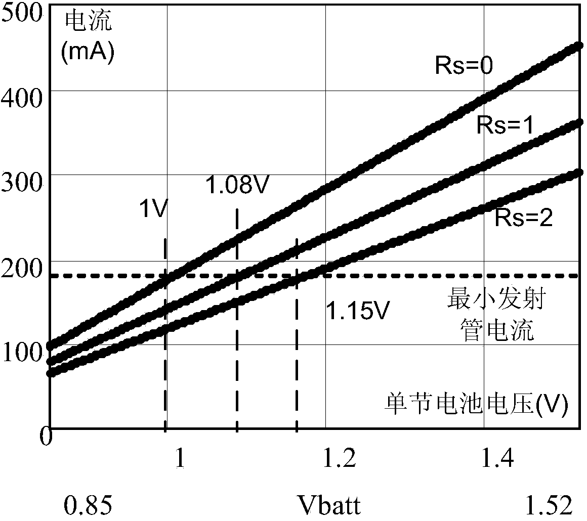
from figure 2 It can be seen from the figure that in order to meet the minimum emitter current, the cut-off voltage of the battery discharge increases with the increase of the current-limiting resistance under different current-limiting resistors, resulting in that the battery capacity cannot be fully utilized.
When the battery voltage is high, the current flowing through the infrared emitting tube is too large, which will cause the battery to discharge too fast and easily damage the emitting tube.
For example, when the current-limiting resistor Rs is 2 ohms, the cut-off voltage of the battery is 1.15V, resulting in a considerable part of the battery capacity being unusable
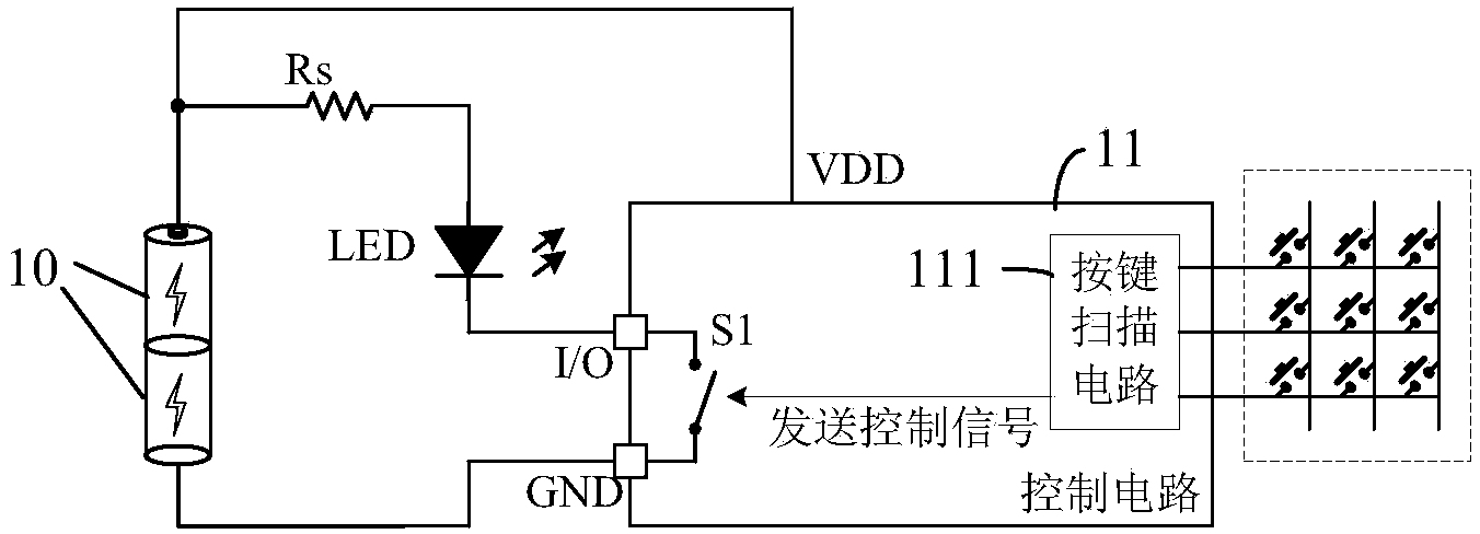
[0008] It can be seen that the traditional power supply circuit requires two or more batteries connected in series to supply power. This power supply method has the problem that the battery capacity cannot be fully utilized, resulting in increased use costs, waste of resources, and environmental pollution.

Method used


Image

  • Device for supplying power through battery and power supply method of device
  • Device for supplying power through battery and power supply method of device
  • Device for supplying power through battery and power supply method of device

Examples


Embodiment approach

[0127] In the step-down DC / DC conversion circuit with high battery power supply, as mentioned above, since the main power consumption equipment in the device is the load such as the launch tube, a suitable voltage V1 is provided when the launch is required. , so that the current flowing through the emission tube reaches a set value, which may be the minimum current that satisfies the emission intensity requirement. When no input signal is detected, that is, when no signal is sent, no current flows through the launch tube, and the main power consumption equipment is turned off. Therefore, the power supply voltage does not affect the power consumption of the system, that is, a high voltage is provided. It also does not increase the power consumption of the device. As another implementation mode, it is even possible to further reduce power consumption by turning off the step-down DC-DC converter and directly using a higher battery voltage for power supply. The implementation mode...


PUM


Abstract

The invention provides a device for supplying power through a battery and a power supply method of the device. The device comprises a control circuit, a direct current / direct current conversion circuit and a power utilization circuit, wherein the control circuit is used for detecting an input signal and generating a control signal used for instructing the work state of the device based on the input signal; an input port of the direct current / direct current conversion circuit is used for being connected with a positive electrode and a negative electrode of the battery, the direct current / direct current conversion circuit receives the control signal and converts the input voltage of the input port into the output voltage, responds to the control signal and instructs the device to be in the non-standby state, so that the voltage value of the output voltage generated by the direct current / direct current conversion circuit is a first voltage; the direct current / direct current conversion circuit responds to the control signal and instructs the device to be in the standby state, so that the voltage value of the output voltage generated by the direct current / direct current conversion circuit is a second voltage different from the first voltage; the power utilization circuit is connected with an output port of the direct current / direct current conversion circuit so as to receive the output voltage. The battery capacity can be fully used by the device, so that use cost is reduced, and a constant supply current is maintained.

Description

technical field [0001] The invention relates to a battery-powered device and a power supply method thereof, in particular to an energy-saving and environment-friendly low-power device powered by a battery and a power supply method thereof. Background technique [0002] Considering factors such as portability and simplicity, some low-power electronic devices are usually powered by batteries, such as electronic thermometers, electronic sphygmomanometers, remote controls, etc. The battery can be a rechargeable battery (such as a lithium battery) or a dry battery or the like. The common requirement of the above applications is how to efficiently and fully utilize the capacity of the battery to increase the duration of battery power supply. [0003] Taking the remote control of a home appliance as an example, both the human-machine interface circuit and the signal transmission circuit inside it need power supply. In the above-mentioned signal sending circuit, the infrared emiss...

Claims


Application Information

Patent Timeline
IPC IPC(8): H02J7/00H02M3/156
CPCY02B70/10
Inventor 郑尊标张军明
Owner HANGZHOU SILAN MICROELECTRONICS
Learn More