
PID-resistant solar cell manufacturing method

The invention relates to a technology for solar cells and a manufacturing method, which can be applied to circuits, photovoltaic power generation, electrical components, etc., and can solve the problems of reducing the anti-reflection effect of silicon nitride and silicon oxide composite films, reducing the utilization rate of solar cells, and affecting the efficiency of solar cells. , to achieve good surface passivation effect, improve photoelectric conversion efficiency, excellent anti-PID effect

Active Publication Date: 2014-07-23
CSI CELLS CO LTD
View PDF5 Cites 13 Cited by
  • Summary
  • Abstract
  • Description
  • Claims
  • Application Information

AI Technical Summary

Problems solved by technology

However, the problems brought about by thicker silicon oxide films are: first of all, it affects the efficiency of the process. Whether it is PECVD or thermal oxidation, it will take a long time to process a large thickness of silicon oxide film.
Secondly, since the refractive index of the silicon oxide film is small

Method used


Image

  • PID-resistant solar cell manufacturing method
  • PID-resistant solar cell manufacturing method

Examples

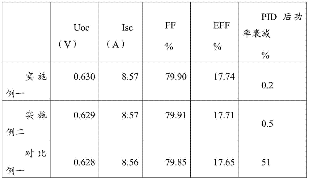

Embodiment 1

[0055] A method for preparing an anti-PID film by using ultraviolet excited ozone oxidation, the steps of which include:

[0056] (1) The diffused silicon wafer is etched to remove the edge, and the phosphosilicate glass layer is cleaned and removed;

[0057] Among them, HF was used for cleaning, the volume concentration of HF solution was 4%, the solution temperature was 20°C, and the cleaning time was 200s;

[0058] (2) After 15 minutes, the diffusion surface of the silicon wafer is irradiated with ultraviolet rays with a wavelength of 172nm and a light intensity of 100W / m2, and compressed air with a flow rate of 10sccm is passed around the silicon wafer, and the temperature of the silicon wafer is 20℃. The distance between the surface of the wafer is 0.5cm, the processing time is 5s, the residual organic matter on the surface of the silicon wafer is removed, and the oxide film is grown to a thickness of 0.6nm;

[0059] (3) After 10min, the silicon nitride film is deposited...

Embodiment 2

[0062] A method for preparing an anti-PID film using ultraviolet light, the steps comprising:

[0063] (1) The diffused silicon wafer is etched to remove the edge, and the phosphosilicate glass layer is cleaned and removed;

[0064] Among them, HF was used for cleaning, the volume concentration of HF solution was 5%, the solution temperature was 21°C, and the cleaning time was 55s;

[0065] (2) After 5s, use ultraviolet rays with a wavelength of 185nm and a light intensity of 200W / m2 to irradiate the diffusion surface of the silicon wafer. The compressed air with a flow rate of 8sccm is passed around the silicon wafer, and the temperature of the silicon wafer is 22°C. The ultraviolet rays pass through the compressed air and reach the silicon wafer. The distance from the surface of the wafer is 0.8cm, the processing time is 8s, the residual organic matter on the surface of the silicon wafer is removed, and the oxide film is grown to a thickness of 0.8nm

[0066] (3) after 15mi...


PUM

PropertyMeasurementUnit
Light intensityaaaaaaaaaa
Thicknessaaaaaaaaaa
Thicknessaaaaaaaaaa

Abstract

The invention discloses a PID-resistant solar cell manufacturing method. The method includes the steps that under the room temperature, ultraviolet light penetrates through compressed air or oxygen with the thickness ranging from 0.2 cm to 1 cm and irradiates the diffusion surface of a silicon wafer, and then an oxidation film with the thickness ranging from 0.5 nm to 1 nm is grown. The silicon oxide layer can meet the requirement for PID resistance under the condition that the silicon oxide layer is extremely thin, and therefore the problem that due to the fact that the silicon oxide layer is too thick, the reflection reduction effect is lowered is solved. The solar cell product perfectly solves the contradictory problem between PID resistance and the light utilization ratio. Meanwhile, the oxide layer manufactured through the method has a good surface passivation effect, and the photoelectric conversion efficiency of the solar cell piece can be improved. The PID-resistant solar cell manufacturing method is simple in process and high in film forming speed, the film thickness can be automatically controlled, the thickness of the formed film can be controlled without special means, the practicability of the whole process is greatly improved, and an effective path is provided for large-scale industrial production.

Description

technical field [0001] The invention belongs to the field of manufacturing crystalline silicon solar cells, and in particular relates to a method for manufacturing a solar cell with anti-PID effect. Background technique [0002] The PID (Potential Induced Degradation) effect is called the high-voltage induced attenuation effect, and it is a relatively new attenuation effect that has appeared in the photovoltaic field in recent years. With the gradual promotion and application of photovoltaic grid-connected systems, the system voltage is getting higher and higher, commonly used are 600V and 1000V. The pressure of the cells inside the module relative to the ground is getting higher and higher, and some even reach 600-1000V. Generally, the aluminum frame of the module is required to be grounded, so that a high voltage of 600-1000V is formed between the battery sheet and the aluminum frame. Generally speaking, during the lamination process of component encapsulation, the struc...

Claims


Application Information

Patent Timeline
IPC IPC(8): H01L31/18H01L21/02H01L21/316
CPCH01L21/02164H01L21/02227H01L31/1804H01L31/1868Y02E10/547Y02P70/50
Inventor 万松博王栩生章灵军
Owner CSI CELLS CO LTD
Learn More