
Gas intake system and substrate processing equipment

A technology of air intake system and air inlet, applied in the field of microelectronics, can solve the problems of low efficiency, limited shortening of the intake pipeline 20, and long exhaust time of residual gas, so as to improve process efficiency, shorten exhaust time, The effect of improving efficiency

Active Publication Date: 2014-07-23
BEIJING NAURA MICROELECTRONICS EQUIP CO LTD
View PDF2 Cites 7 Cited by
  • Summary
  • Abstract
  • Description
  • Claims
  • Application Information

AI Technical Summary

Problems solved by technology

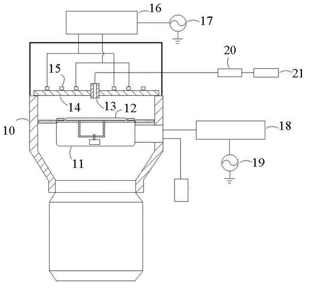
[0011] The above-mentioned air intake system inevitably has the following problems in practical applications, that is, when the deposition exhaust or etching exhaust steps are performed, the residual gas in the intake pipeline 20 must flow through the entire intake pipeline 20 and then be exhausted. into the reaction chamber 10, and then discharged from the reaction chamber 10, resulting in a longer exhaust time for the residual gas, and, because the above-mentioned inlet pipeline 20 has only one dry path, the gas required for subsequent operations must wait The gas remaining in the gas inlet pipeline in one operation can only be passed into the reaction chamber after it is exhausted, which leads to the low efficiency of the above gas inlet system for switching the gas types into the reaction chamber, thereby reducing the process efficiency of the substrate processing equipment. efficiency
Although it is possible to shorten the time for residual gas to be discharged from the intake pipeline 20 by shortening the length of the intake pipeline 20, due to the limitation of the space occupied by the radio frequency system, heating system, etc., which are arranged near the gas nozzle 13, the intake pipeline 20 The shortening of the length is limited, so that the time for exhausting the residual gas in the intake pipeline 20 cannot be effectively shortened

Method used


Image

  • Gas intake system and substrate processing equipment
  • Gas intake system and substrate processing equipment
  • Gas intake system and substrate processing equipment

Examples


Embodiment Construction

[0031] In order for those skilled in the art to better understand the technical solutions of the present invention, the air intake system and substrate processing equipment provided by the present invention will be described in detail below with reference to the accompanying drawings.

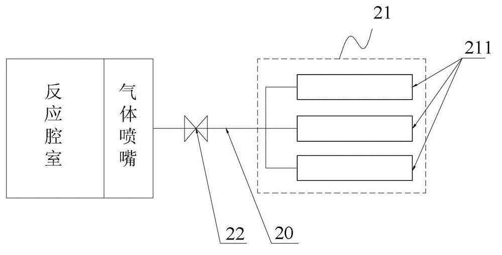
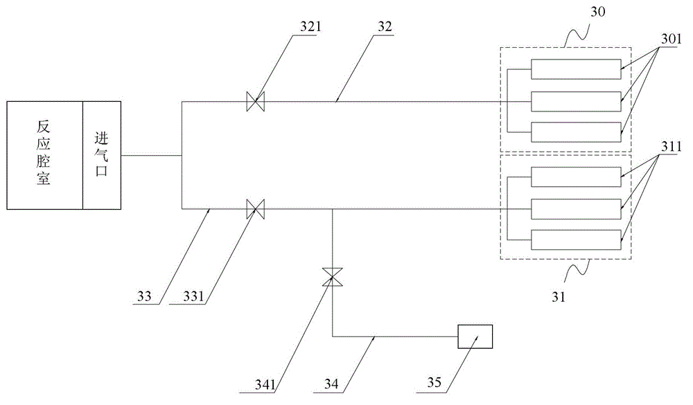
[0032] figure 2 The schematic diagram of the air intake system provided by the first embodiment of the present invention. see figure 2The air intake system includes an air inlet connected to the reaction chamber, an air intake pipeline, an exhaust pump 35 and at least one gas source, and the gas types of different gas sources are different. Wherein, the gas inlet can be a gas nozzle, a through hole, etc., which can communicate with the reaction chamber; the gas source includes at least one carrier gas source and at least one reaction gas source; the carrier gas refers to the The gas that does not physically or chemically interact with the substrate during the etching process and is used to ...


PUM


Abstract

The invention provides a gas intake system and a set of substrate processing equipment. The gas intake system comprises a gas inlet communicated with a reaction cavity, a gas intake pipeline and at least one gas source, wherein different gas sources provide different types of gases. The gas intake pipeline comprises a main line, main line valves, branches and branch valves, wherein the main lines are connected between the gas inlet and all the gas sources and used for delivering gases output by the gas sources into the reaction cavity through the gas inlet; the main line valves are arranged on the main lines and used for connecting or disconnecting the main lines; one ends of the branches are connected into the main lines in series and located on the upstream of the main line valves, and the branches are used for discharging gases in the main lines when the main line valves are closed; the branch valves are arranged on the branches and used for connecting or disconnecting the branches. According to the gas intake system, the efficiency for switching the types of gases in the reaction cavity is high, and thus the technological efficiency can be improved.

Description

technical field [0001] The invention relates to the technical field of microelectronics, in particular to an air intake system and substrate processing equipment. Background technique [0002] At present, the deep silicon etching process has gradually become one of the hottest processes in the field of MEMS processing and TSV technology, and the main difference between the deep silicon etching process and the general silicon etching process is: the etching process of the deep silicon etching process The depth is much greater than that of the general silicon etching process. The etching depth of the deep silicon etching process is generally tens of microns or even hundreds of microns, while the etching depth of the general silicon etching process is less than 1 micron. To etch a silicon material with a thickness of tens of microns, the deep silicon etching process is required to have a faster etching rate, a higher selectivity ratio and a larger aspect ratio. [0003] For th...

Claims


Application Information

Patent Timeline
IPC IPC(8): H01L21/67H01L21/3065
CPCC23C16/455C23F1/08H01L21/6719
Inventor 杨盟
Owner BEIJING NAURA MICROELECTRONICS EQUIP CO LTD
Learn More