
A regenerative electric furnace flue gas waste heat recovery system

A flue gas waste heat recovery system technology, applied in furnaces, waste heat treatment, steam superheating, etc., can solve the problems of low waste heat recovery efficiency, large pressure fluctuations, and difficulty in matching steam users, and achieve the effect of improving utilization efficiency

Active Publication Date: 2016-04-20
SHANGHAI BAOSTEEL ENERGY TECH
View PDF6 Cites 3 Cited by
  • Summary
  • Abstract
  • Description
  • Claims
  • Application Information

AI Technical Summary

Problems solved by technology

Although the waste heat recovery system is equipped with a heat accumulator, it is difficult to match suitable steam users due to large fluctuations in the steam flow rate and pressure recovered by the electric furnace, which ultimately affects the actual effect of the waste heat recovery of the electric furnace, resulting in low waste heat recovery efficiency

Method used


Image

  • A regenerative electric furnace flue gas waste heat recovery system
  • A regenerative electric furnace flue gas waste heat recovery system
  • A regenerative electric furnace flue gas waste heat recovery system

Examples


Embodiment Construction

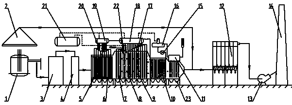
[0056] Referring to the drawings showing the present embodiment, it will be described in more detail below. However, the invention may be embodied in many different forms and should not be construed as limited to the embodiments set forth herein. Rather, these embodiments are provided so that this disclosure will be thorough and complete, and will fully convey the scope of the invention to those skilled in the art. In these drawings, the size and relative sizes of layers and regions may be exaggerated for clarity.

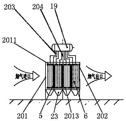
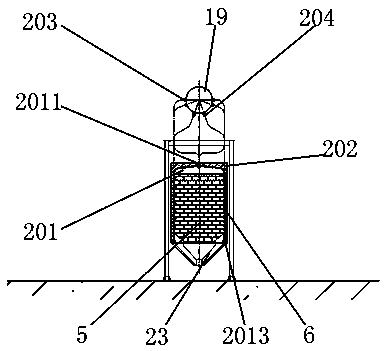
[0057] refer to Figure 1-3 As shown, the present invention provides a regenerative electric furnace flue gas waste heat recovery system, which is used to recover intermittent electric furnace flue gas waste heat to generate stable and continuous superheated steam, mainly including electric furnace 1, regenerative water-cooled settling chamber 20, convective heat exchange Waste heat boiler 17, feed water heater 11, steam accumulator 21, etc. This system can effec...


PUM


Abstract

The invention provides a heat accumulation type electric furnace flue gas waste heat recovery system which comprises a perpendicular type connecting flue, a heat accumulation type water-cooling settling chamber, a heat convection waste heat boiler, a feed water heater, a steam heat accumulator and the like. After flue gas inside a combustion settling chamber passes through the perpendicular type connecting flue, the temperature and the flow rate of the flue gas are preliminarily integrated through the heat accumulation type water-cooling settling chamber, and then the flue gas sequentially enters the heat convection waste heat boiler and is exhausted to the atmosphere after the flue gas is cooled through the feed water heater and dust of the flue gas is removed through a dust remover. Raw water is heated through the feed water heater and then enters a deaerator for removing oxygen in the raw water. Then, the raw water flows through the heat convection waste heat boiler and the heat accumulation type water-cooling settling chamber and generates saturated steam to be fed into the steam heat accumulator. The steam enters a superheater after being buffered by the steam heat accumulator, and the superheated steam is output stably in a superheated mode. According to the heat accumulation type electric furnace flue gas waste heat recovery system, due to the fact that the two peak clipping trough levelling measures of the heat accumulation type water-cooling settling chamber and the steam heat accumulator are set, flue gas waste heat, generated by an electric furnace, with unstable fluctuations passes through the heat accumulation type electric furnace flue gas waste heat recovery system so as to stably and efficiently output the superheated steam.

Description

technical field [0001] The invention relates to the technical field of industrial waste heat recovery and utilization, in particular to a waste heat recovery system for regenerative electric furnace flue gas. Background technique [0002] At present, in order to further reduce the cost of electric furnace steelmaking, domestic iron and steel enterprises generally use molten iron mixed with scrap steel smelting mode in the electric furnace process, and the ratio of molten iron can be as high as 70~90%, showing the trend of "converterization" of electric furnace equipment. With the increase of the proportion of molten iron in the electric furnace and the reduction of the amount of scrap steel, the concentration of CO in the flue gas, temperature and flue gas of the electric furnace increases, and it is more meaningful to recover the waste heat of the flue gas of the electric furnace. [0003] Due to the periodic influence of electric furnace smelting, the intermittent waste he...

Claims


Application Information

Patent Timeline
Patent Type & Authority Patents(China)
IPC IPC(8): F27D17/00F22B1/18F22G1/00
CPCY02P10/25Y02P80/15
Inventor 陈志良曹先常杨文滨孔令斌
Owner SHANGHAI BAOSTEEL ENERGY TECH
Learn More