
Double-acting servo pressure cylinder for press machine

A technology for booster cylinders and presses, applied in the directions of fluid pressure actuation devices, fluid pressure actuation system components, mechanical equipment, etc. The effect of response speed and operation speed, improving flexibility and control accuracy, and reducing design cost

Inactive Publication Date: 2014-07-23
XI AN JIAOTONG UNIV
View PDF6 Cites 9 Cited by
  • Summary
  • Abstract
  • Description
  • Claims
  • Application Information

AI Technical Summary

Problems solved by technology

According to the working principle, the press can be divided into two types: hydraulic press and mechanical press. The ordinary hydraulic press is supplied with oil by the oil pump. The hydraulic oil is always in a high-pressure state during the working stage. Since there is no load in the idle stroke stage, the high-pressure oil will pass through the hydraulic valve and the hydraulic oil. Road unloading, the pressure loss is basically converted into heat, resulting in an increase in the temperature of the hydraulic oil, resulting in oil leakage and a large amount of energy loss
Compared with the hydraulic press, the mechanical press does not have the problem of wasting energy in the idle stroke, and the idle stroke speed is generally faster, but the stamping curve of the mechanical press is generally fixed after the design and manufacture, and for some stamping curves there are special Due to the required process, mechanical presses are often prone to problems such as wrinkles and cracks, and the design and manufacturing costs of mechanical presses are relatively high. Due to the limitation of mechanical structures, the design tonnage of mechanical presses generally cannot be large
[0003] With the continuous development of modern manufacturing technology, presses are required to have high control precision and response speed, while retaining large load characteristics. Due to the above problems, traditional mechanical presses and hydraulic presses have limited their application.

Method used


Image

  • Double-acting servo pressure cylinder for press machine
  • Double-acting servo pressure cylinder for press machine
  • Double-acting servo pressure cylinder for press machine

Examples


Embodiment Construction

[0019] The present invention will be further described below in conjunction with the accompanying drawings.

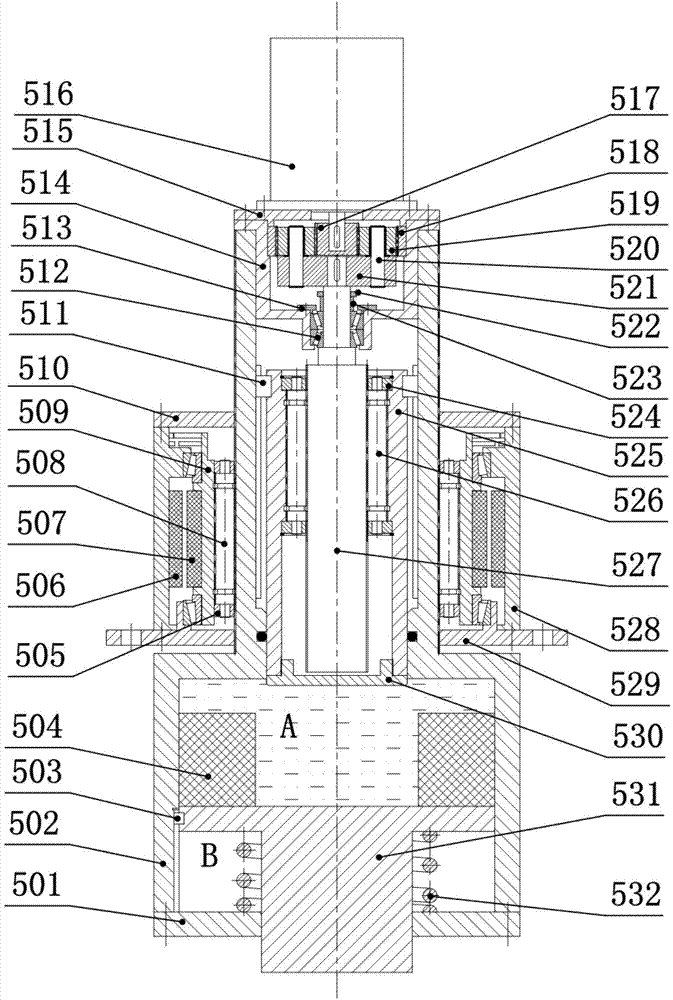
[0020] refer to figure 1 , a double-acting servo pressurized cylinder for a press, the fuselage mechanism is a three-beam four-pillar type, the fuselage mechanism includes a column 2, the column 2 is hollow, the tie rod 6 runs through the column 2, the outer surface of the column 2 is smooth, and the slider 3 is on the column 2 slides up and down, and the lock nuts 7 at both ends of the tie rod 6 fix the four uprights 2 between the beam 4 and the base 1, the double-action servo booster cylinder 5 is fixed on the beam 4 by bolts, and the double-action servo booster cylinder 5 The piston rod is connected with the slider 3.

[0021] refer to figure 2 and image 3 , the double-action servo booster cylinder 5, the installation quantity is determined according to the actual nominal pressure, the double-action servo booster cylinder 5 includes an idle stroke device and a ...


PUM


Abstract

A double-acting servo pressure cylinder for a press machine comprises an idle stroke device and a working stroke device. The idle stroke device is designed inside an outer cylinder body. An idler stroke servo motor rotor and planetary roller lead screw nuts are designed together. The nuts drive an inner cylinder body through rollers to reciprocate mechanically inside an idle stroke motor. The working stroke device is designed inside the inner cylinder body. A planetary reduction gear, a planetary roller lead screw device, a pressure boost cavity and a stroke cavity are sequentially arranged on the inner cylinder body from top to bottom. Both an idle stroke and a working stroke are powered by a servo motor. According to the double-acting servo pressure cylinder for the press machine, the idle stroke and the working stroke are independently controlled, energy consumption is reduced, flexibility and control precision of the press machine are improved, and the design cost of the press machine is reduced.

Description

technical field [0001] The invention relates to a booster cylinder, in particular to a double-acting servo booster cylinder for a press. Background technique [0002] The press is a pressure processing equipment that deforms the blank to meet the expected design requirements by applying pressure to the blank. It can realize various forming processes such as forging, stamping, cold extrusion, and deep drawing. It has strong versatility and is widely used in various industries. Industry. According to the working principle, presses can be divided into hydraulic presses and mechanical presses. Ordinary hydraulic presses are supplied with oil by an oil pump. The hydraulic oil is always in a high-pressure state during the working stage. Since there is no load in the idle stroke stage, the high-pressure oil will pass through the hydraulic valve and the hydraulic oil. When the road is unloaded, the pressure loss is basically converted into heat, which causes the temperature of the ...

Claims


Application Information

Patent Timeline
IPC IPC(8): F15B21/08F15B15/20F15B15/08
Inventor 赵升吨孟德安李靖祥范淑琴李雪陈超
Owner XI AN JIAOTONG UNIV
Learn More