A transmitter drive circuit for a photoelectric sensor

A photoelectric sensor and drive circuit technology, applied in the direction of electric lamp circuit layout, light source, electric light source, etc., can solve the problems of sensor pollution, LED current change, luminous brightness instability, etc., and achieve the effect of improving work stability and reliability

Inactive Publication Date: 2019-04-05
SHENZHEN YIHUA COMP +2
View PDF6 Cites 0 Cited by
  • Summary
  • Abstract
  • Description
  • Claims
  • Application Information

AI Technical Summary

Problems solved by technology

[0004] 1. The LED current is easy to change due to the change of the power supply, and the luminous brightness is unstable, which affects the accuracy of the detection at the receiving end;
[0005] 2. The LED current cannot be adjusted by programming. After long-term use, due to the pollution or aging of the sensor, it is often necessary to adjust the current of the LED light to make it still work normally, but this solution cannot achieve this function.

Method used


Image

  • A transmitter drive circuit for a photoelectric sensor
  • A transmitter drive circuit for a photoelectric sensor
  • A transmitter drive circuit for a photoelectric sensor

Examples


Embodiment Construction

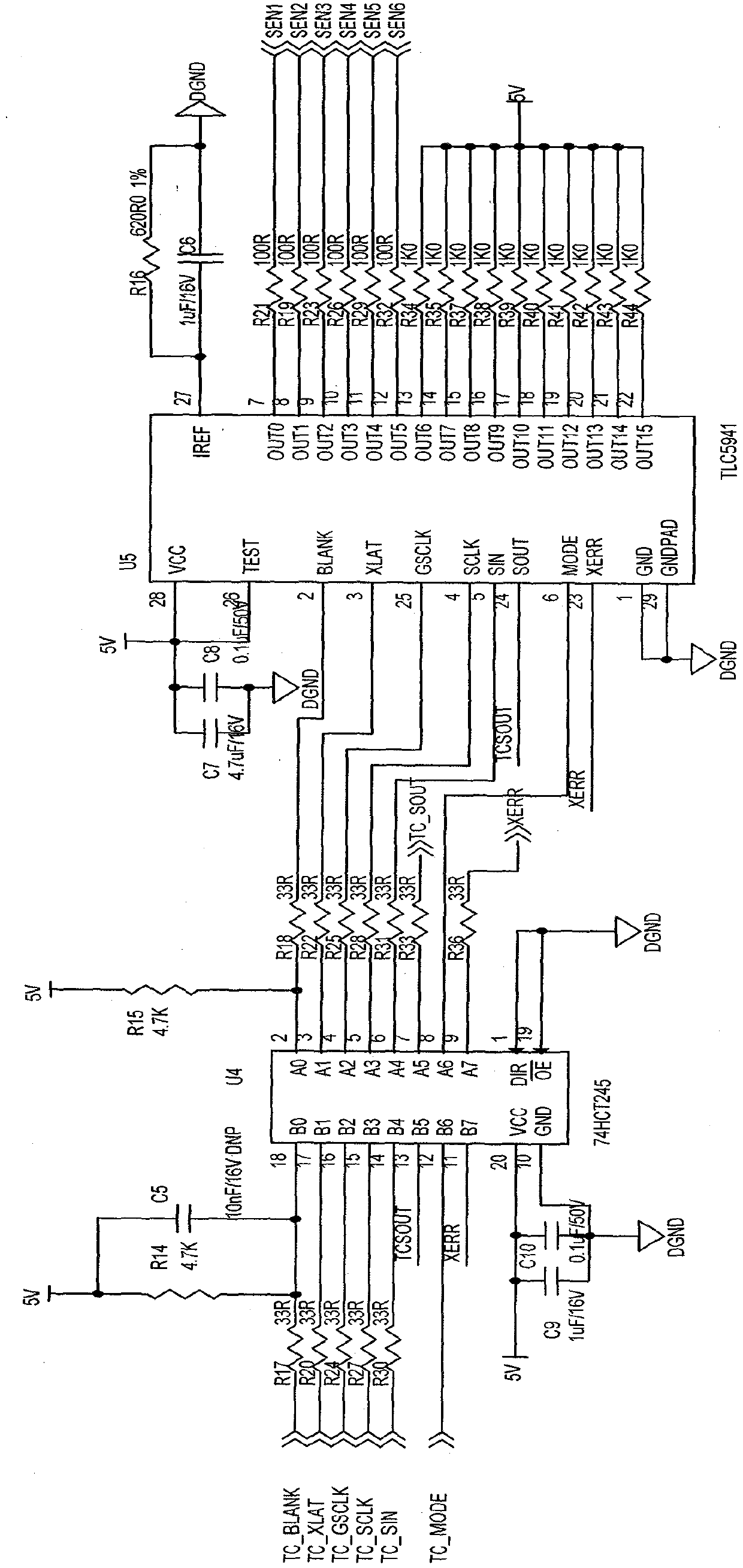
[0018] Examples, see image 3 . The transmitter drive circuit of the photoelectric sensor of this embodiment includes:

[0019] One LED driver chip TLC5941 U5 and one signal driver chip 74HCT245 U4; among them,

[0020] Connect a matching resistor R17, R20, R24, R27 and R30 to the signal line of the input pin B0-B4 of the signal driver chip 74HCT245 U4, and connect a pull-up resistor R14 and R14 between the resistor R17 and the input pin B0 Capacitor C5 and the other end of resistor R17 are connected to the 5V power supply; the output pins A0-A4 of the signal driver chip 74HCT245 U4 are respectively connected to the input pins BLANK, XLAT, GSCLK, SCLK and SIN of the LED driver chip TLC5941 U5. A matching resistor R18, R22, R25, R28 and R31 are respectively connected in series in the connection signal line, and a pull-up resistor R15 is also connected in parallel between the output pin A0 and the resistor R18, and the other end of the pull-up resistor R15 is connected to the ...


PUM


Abstract

The invention discloses a photoelectric sensor transmitting terminal driving circuit, and aims to overcome the defect that an existing photoelectric sensor transmitting terminal driving circuit cannot make the driving current of an LED to be constant current, and cannot adjust the current magnitude through a compiled program. The photoelectric sensor transmitting terminal driving circuit comprises an LED driving chip TLC 5941 and a signal driving chip 74 HCT 245 which is connected with the LED driving chip TLC 5941 through signals; the signal driving chip 74 HCT 245 is used for driving the signals and guaranteeing the quality of the signals; the LED driving chip TLC 5941 is used for driving a transmitting terminal of a photoelectric sensor, can drive 16 sensor transmitting terminals simultaneously with the driving current being constant current, can allocate an internal memory register of the driving chip so as to achieve current adjustment, and can control the switch-on and switch-off of a current source. The photoelectric sensor transmitting terminal driving circuit can be applied to the transmitting terminal driving circuits of various photoelectric sensors.

Description

technical field [0001] The invention relates to a driving circuit, in particular to a driving circuit in a photoelectric sensor. Background technique [0002] Photoelectric sensors such as figure 1 The shown includes a transmitting end and a receiving end. Generally, the transmitting end is a light-emitting LED, and the light can be infrared light or light of other wavelengths. The receiving end is a photosensitive transistor. Its working principle is that the current flowing through the phototransistor is proportional to the received luminous flux. When the luminous flux received by the phototransistor is small, the current flowing between its collector and emitter is also small. When the phototransistor receives When the luminous flux is large, the current flowing between its collector and emitter will also increase. Photoelectric sensors can be used to detect the presence or absence of objects, passing states, running speeds, etc. For photoelectric sensors to be used n...

Claims


Application Information

Patent Timeline
Patent Type & Authority Patents(China)
IPC IPC(8): H05B37/02
Inventor 石鸥吴连玉王应建
Owner SHENZHEN YIHUA COMP
Why Eureka
Try Eureka