
A cladding optical power stripping method of a double-clad optical fiber

A technology of double-clad optical fiber and cladding light, which is applied in the field of optoelectronics, can solve the problems of insignificant ASE suppression effect, attenuation of cladding light power, and increase of light divergence angle, so as to improve beam quality, effective absorption and stripping, The effect of increasing the divergence angle

Active Publication Date: 2016-01-20
DANYANG JUCHEN OPTOELECTRONICS TECH
View PDF7 Cites 0 Cited by
  • Summary
  • Abstract
  • Description
  • Claims
  • Application Information

AI Technical Summary

Problems solved by technology

Its disadvantages are: firstly, it needs a longer absorption length; secondly, the stripping efficiency is low, especially for cladding power with small divergence angle; thirdly, the inhibition effect on ASE in the fiber core is not obvious
Chinese Patent Publication No. CN102208741A, named as a high-efficiency residual pump light attenuation method, is to remove a section of outer cladding and coating layer of the double-clad optical fiber at the output end of the fiber laser, and then make a long-period optical fiber in the middle of the section of optical fiber Grating, whose bandstop wavelength is matched to the wavelength of the pump light to attenuate the remaining pump light in the inner cladding, but not the signal light from the fiber laser
The disadvantage is that the ASE suppression effect in the fiber core is not obvious
The role of the first section of coating material is to increase the divergence angle of light in the cladding; the role of the second section of coating material is to attenuate the cladding optical power Improvement, but the structure is complex and the process is difficult to control
At the same time, the suppression effect on ASE in the fiber core is not obvious

Method used


Image

  • A cladding optical power stripping method of a double-clad optical fiber
  • A cladding optical power stripping method of a double-clad optical fiber
  • A cladding optical power stripping method of a double-clad optical fiber

Examples


Embodiment 1

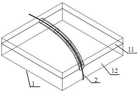
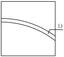
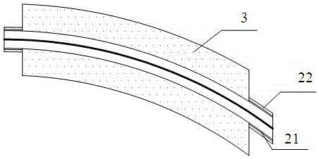
[0022] An all-fiber laser strips off a section of outer cladding and coating layer of the double-clad fiber after the fiber grating at the output end, and the length of the stripped section is 64mm. The core diameter of the double-clad optical fiber 2 involved here is 25 μm, NA~0.06; the inner cladding diameter is 250 μm, NA~0.46, and the diameter of the high-refractive index organic coating is about 2.5 mm, and the refractive index is 1.45. The metal with good thermal conductivity is used to make the above-mentioned mechanical element 1. The size of the substrate is 60mm×60mm×10mm, and a curved semi-cylindrical groove 13 with a diameter slightly less than 2.5mm is milled on its upper surface, the radius of curvature is 100mm, and the length is 50mm. The size of the cover plate 12 of the mechanical element 1 is 60mm×60mm×5mm, and the same groove is also milled on its lower surface. In this way, when the cover plate 12 is combined with the base plate 11, the close contact betw...


PUM


Abstract

The invention provides a cladding optical power stripping method of a double-cladding fiber. The method comprises the following steps of (1) preparing a mechanical element, (2) removing and recoating a double-cladding fiber outer layer, and (3) placing the double-cladding fiber in the mechanical element. According to the cladding optical power stripping method of the double-cladding fiber, a signal light high order mode and an ASE high order mode in a fiber core can be leaked to cladding, so that amplified spontaneous emission of the fiber core is restrained, and the transmitting mode and the light beam quality of signal light in the fiber core are improved. The divergence angle of light transmitted in the cladding is enlarged, the optical power of the large divergence angle cladding can be more effectively absorbed and stripped, and thus the stripping efficiency is improved. The cladding optical power stripping method of the double-cladding fiber has the advantages that the structure is simple, the manufacturing cost is low, and the method is suitable for mass production.

Description

technical field [0001] The invention relates to a method for stripping cladding light power in a double-clad optical fiber, which belongs to the technical field of optoelectronics. Background technique [0002] Since E.Snitzer first described cladding-pumped fiber lasers in 1988, double-clad fibers have gradually been widely used in the fields of fiber lasers and fiber amplifiers. The emergence of double-clad fibers effectively improves the coupling efficiency and absorption efficiency of pump light in fiber lasers, and greatly improves the output efficiency of fiber lasers. The working principle of cladding pumping technology is: the pump light is injected into the inner cladding of the optical fiber in an oblique manner, and repeatedly passes through the fiber core in the form of refraction, so that the pump light is absorbed by the rare earth ions in the fiber core, and the laser light produced propagates along the fiber core. Ideally, all signal light would be amplifie...

Claims


Application Information

Patent Timeline
Patent Type & Authority Patents(China)
IPC IPC(8): G02B6/245
Inventor 李丰
Owner DANYANG JUCHEN OPTOELECTRONICS TECH
Learn More