Methods And Systems For Operating Gas Turbine Engines

A technology for gas turbines and engines, which is used in gas turbine installations, turbine/propulsion fuel delivery systems, engine components, etc., and can solve problems such as complex and expensive manufacturing of purge systems

Inactive Publication Date: 2014-07-16
GENERAL ELECTRIC CO
View PDF6 Cites 7 Cited by
  • Summary
  • Abstract
  • Description
  • Claims
  • Application Information

AI Technical Summary

Problems solved by technology

However, known purging systems are expensive and complex to manufacture

Method used


Image

  • Methods And Systems For Operating Gas Turbine Engines
  • Methods And Systems For Operating Gas Turbine Engines
  • Methods And Systems For Operating Gas Turbine Engines

Examples


Embodiment Construction

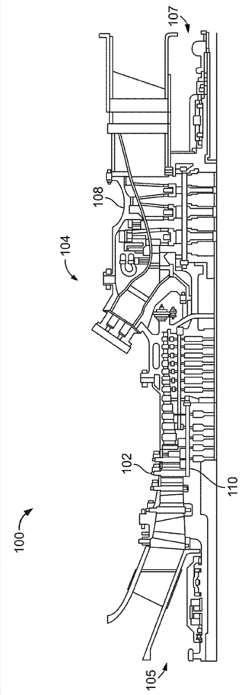
[0070] figure 1 is a schematic diagram of an exemplary gas turbine engine 100 . Engine 100 includes a compressor assembly 102 and a plurality of combustor assemblies 104 . Engine 100 also includes turbine 108 and a common compressor / turbine shaft 110 , sometimes referred to as rotor 110 . Combustor assembly 104 is coupled in flow communication with turbine assembly 108 and with compressor assembly 102 .

[0071] In operation, air enters engine 100 through inlet 105 and flows downstream through compressor assembly 102 such that compressed air is supplied to combustor assembly 104 . The fuel is directed to a combustion zone defined within the combustor assembly 104 ( figure 1 not shown), where fuel is mixed with air and ignited. Combustion gases are generated and channeled to turbine 108 , where thermal energy of the gas flow is converted to mechanical rotational energy and exits engine 100 through outlet 107 . Turbine 108 is rotatably coupled to shaft 110 . As used herein...


PUM


Abstract

Methods and systems for operating a gas turbine engine including a fuel delivery system and a plurality of combustor assemblies are provided. The fuel delivery system comprises a primary fuel circuit configured to continuously supply fuel to each of the plurality of combustor assemblies during a first mode of operation and a second mode of operation. At least one secondary fuel circuit of the fuel delivery system is configured to supply fuel to each of the plurality of combustor assemblies during the second mode of operation. The secondary fuel circuit includes at least one isolation valve coupled in flow communication with each of the plurality of combustor assemblies. The at least one isolation valve facilitates preventing fluid flow upstream into the secondary fuel circuit during the first mode of operation. The fuel delivery system, by using the isolation valve, replaces a purging system in the gas turbine engine.

Description

technical field [0001] Embodiments described herein relate generally to gas turbine engines, and more particularly to methods and systems for operating gas turbine engines. Background technique [0002] Known gas turbine engines generally include a compressor, one or more combustors each including a fuel injection system, and a turbine section. In at least some known engines, the combustors are typically arranged in an annular array around the engine and are interconnected for ignition purposes. The compressor increases the pressure of the inlet air and then directs the pressurized air towards the combustor where it cools the combustion chamber walls and is used in the combustion process. More specifically, in the combustor, compressed air is mixed with fuel, and the mixture is ignited to produce hot combustion gases. [0003] In some known combustion turbines, the turbine may be powered using fuel gas or liquid fuel. Such turbines may have fuel supply systems for both li...

Claims


Application Information

Patent Timeline
Patent Type & Authority Applications(China)
IPC IPC(8): F02C7/22F02C7/232F02C9/40
CPCF02C7/22F02C7/228
Inventor F.T.科德伦S.K.维德纳J.E.普里特查德
Owner GENERAL ELECTRIC CO
Why Eureka
Try Eureka