
Front-view intelligent anti-glare device of vehicle and manufacturing method of anti-glare mirror thereof

A manufacturing method and anti-glare technology, which can be applied to optical observation devices, vehicle parts, optics, etc., can solve the problems of decreased sealing, low volume intrinsic resistivity, and decreased barrier properties of solvent-based electrolytes in ionic conductor layers of packages.

Active Publication Date: 2014-07-09
CHANGZHOU YAPU NEW MATERIALS CO LTD
View PDF16 Cites 12 Cited by
  • Summary
  • Abstract
  • Description
  • Claims
  • Application Information

AI Technical Summary

Problems solved by technology

Conductive adhesive wires are arranged within the sealing width of 2-3mm, the width is 0.5-1mm wide, the thickness is 10-20um, and the length is 250mm. For example, Treebond's 3302B is used, and its volume intrinsic resistivity is very low, reaching 3*10 ~6 Ω·m, but the resistance of the conductive adhesive wire is still as high as 50Ω, and the resistance value must be controlled within the range of 20 ohms, which still affects the response time of the device’s color change switching, and is affected by the addition of conductive adhesive wires in the packaging area. Cross-effect, the actual effective sealing width is reduced, the sealing performance is reduced, and the water and oxygen barrier properties of the solvent-based electrolyte in the ion conductor layer of the package are also reduced, which ultimately affects the life of the device

Method used


Image

  • Front-view intelligent anti-glare device of vehicle and manufacturing method of anti-glare mirror thereof
  • Front-view intelligent anti-glare device of vehicle and manufacturing method of anti-glare mirror thereof
  • Front-view intelligent anti-glare device of vehicle and manufacturing method of anti-glare mirror thereof

Examples


Embodiment 1

[0076] (Example 1, a vehicle front-view intelligent anti-glare device)

[0077] Such as Image 6 Shown; A kind of vehicle forward-looking intelligent anti-glare device has control device 1 and anti-glare mirror 2 installed in the bracket 4; the output end of control device 1 is connected with the input end of anti-glare mirror 2;

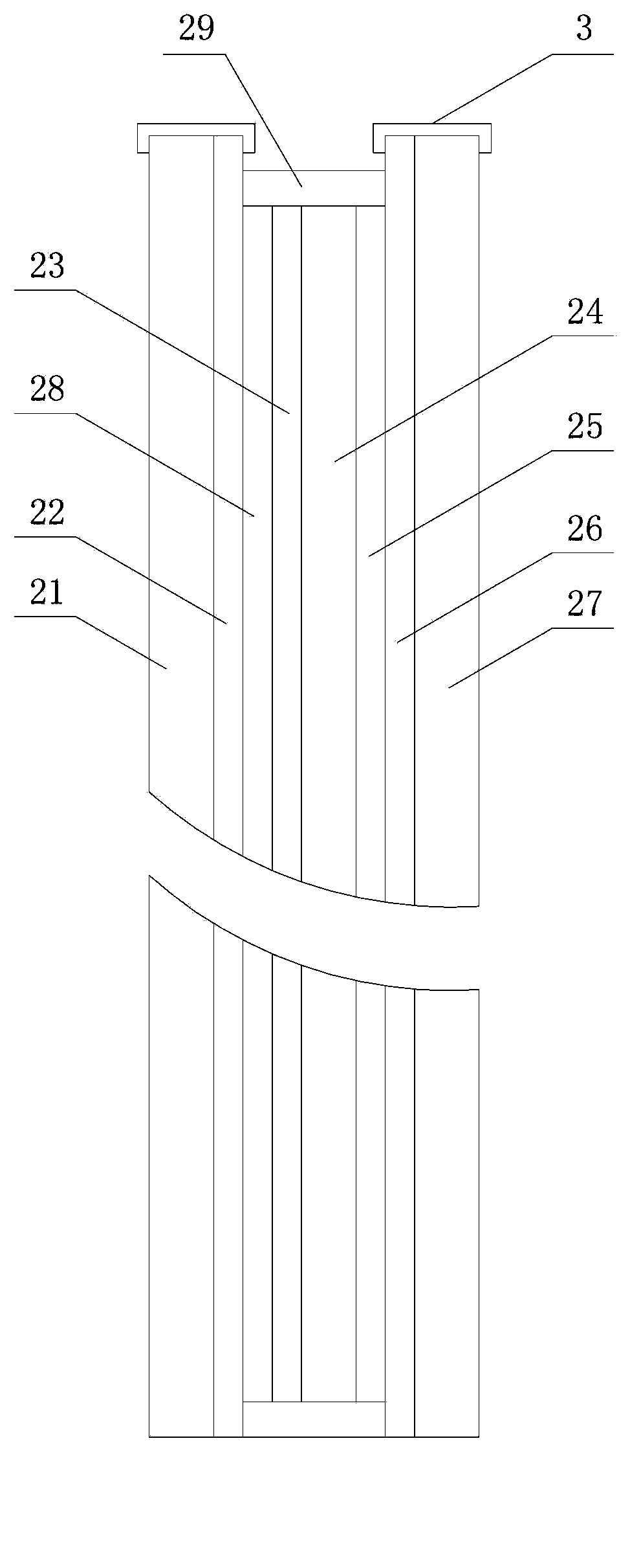
[0078] Such as figure 2 As shown, the anti-glare mirror 2 has a first substrate 21, a conductive layer 22, a monomer molecular coating 28, an electrochromic coating 23, an ion conductor layer 24, an ion storage layer 25, an ion conduction layer 26, and a first layer stacked in sequence. Two substrates 27; the first substrate 21 and the second substrate 27 are provided with a sealant layer 29 cured by ultraviolet rays or heat-cured, the first substrate 21 and the second substrate 27 are rigid transparent substrates; the ion conductor layer 24 is liquid type.

[0079] The electrochromic coating 23 of the anti-glare mirror 2 is a polymer electrochr...

Embodiment 2

[0088] (Example 2, a vehicle front-view intelligent anti-glare device)

[0089] Such as Figure 10 As shown, the intelligent electro-induced gradient anti-glare mirror 2 is fixed on the bracket, and the bracket is fixed on the front windshield through a vacuum suction cup. Adjust the height of the suction cup on the front windshield to ensure that the distance from the driver's eyes to the anti-glare mirror 2 is 200-400 mm, and the line formed by the bottom edge of the anti-glare mirror 2 and the driver's eyes falls about 30 meters in front of the road . This structure also ensures that the intelligent electro-gradient anti-glare device plays an anti-glare function.

[0090] The working principle of the present invention is: when meeting cars at night and encountering glare, the glare sensor 122 and the ambient light sensor 123 generate photocurrent after receiving light, and the MCU microprocessor 11 in the control device simulates the voltage produced by the photocurrent. ...

Embodiment 3

[0100] (Example 3, a method for manufacturing an anti-glare mirror of a forward-looking intelligent anti-glare device for a vehicle)

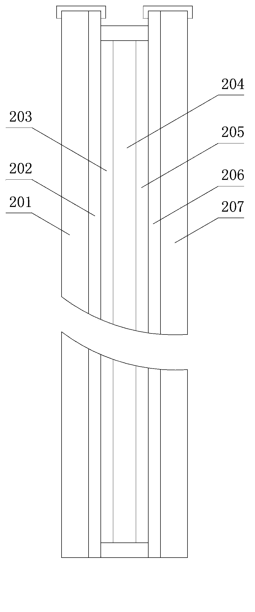
[0101] The anti-glare mirror 2 has a first substrate 21, a conductive layer 22, an electrochromic coating 23, an ion conductor layer 24, an ion storage layer 25, an ion conduction layer 26 and a second substrate 27 stacked in sequence; it is characterized in that: the conduction layer There is also a monomer molecular coating 28 between the 22 and the electrochromic coating 23; the manufacture method of the anti-glare mirror 2 comprises the following steps:

[0102] a. Make the first substrate 21 and the second substrate 22: put the ITO conductive glass with a square resistance of 12 ohm / □ and a light transmittance of 90% on a special-shaped glass cutting machine and cut them into shapes. The sizes are 26.5*7.5cm and 27*7.2 cm, then, use DI deionization and water-based cleaning agent to clean it on the ultrasonic machine several times; finally,...


PUM

PropertyMeasurementUnit
Granularityaaaaaaaaaa

Abstract

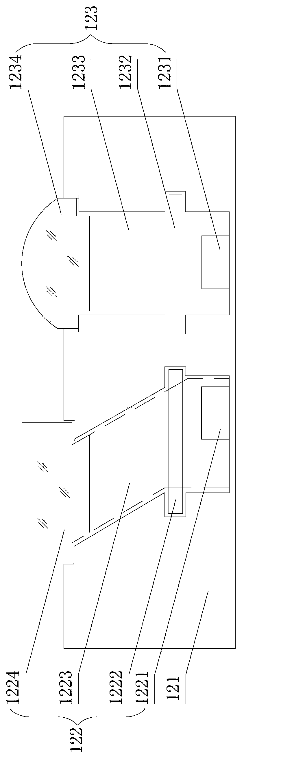
The invention relates to a front-view intelligent anti-glare device of a vehicle and a manufacturing method of an anti-glare mirror thereof. The front-view intelligent anti-glare device of the vehicle is provided with a control device installed in the support and the anti-glare mirror. The output end of the control device is connected with the input end of the anti-glare device. The control device is provided with an MCU microprocessor, a light sensor, a power supply module and a power supply output control module. The light sensor is provided with a casing and a light sensing mechanism arranged in the casing. The light sensing mechanism is provided with a glare sensor and an environment light sensor. The input end of the MCU microprocessor is respectively connected with the output end of the environment light sensor, the output end of the glare sensor and the output end of the power supply module, and the output end of the MCU microprocessor is connected with the input end of a power supply control module. The output end of the power supply control module is used for being connected with the input end of the anti-glare mirror through an electrode. A monomer molecular coating is added for the anti-glare mirror. The front-view intelligent anti-glare device senses the intensity through the light sensor, the MCU microprocessor receives, processes and sends signals to eliminate glare influence, and the running safety is ensured.

Description

technical field [0001] The invention relates to the technical field of anti-glare mirrors for automobiles, and in particular to a vehicle front-view intelligent anti-glare device and the manufacture of the anti-glare mirror for vehicles meeting at night and shading during the day, eliminating the influence of glare, and ensuring driving safety. method. Background technique [0002] The glare of cars meeting cars at night is a key factor and an important issue affecting driving safety, especially when the party with weak headlights is under the strong illumination of the headlights of the other party, it will form a blind spot in the process of meeting cars and cannot see its own party at all. The road conditions are very dangerous, and major traffic accidents often occur as a result. Even if both sides use the far and near light switching method to reduce the impact of the headlights, the glare still exists and affects driving safety. [0003] In order to solve this proble...

Claims


Application Information

Patent Timeline
IPC IPC(8): B60R1/10G02F1/153
Inventor 徐春叶罗汉丰郑建明
Owner CHANGZHOU YAPU NEW MATERIALS CO LTD
Learn More