A Decoupled Reactor Based on Atmosphere Switching
A decoupling reactor and atmosphere technology, applied in the field of high-temperature chemical reaction analysis and testing, can solve the problems of inability to analyze solid carbon-based fuel multi-stage in-situ decoupling reactions, small gas sampling delay, small gas flow switching back mixing, etc. Achieve short delay time of atmosphere switching, small airflow switching backmixing, and satisfy the effect of sufficient airflow preheating
- Summary
- Abstract
- Description
- Claims
- Application Information
AI Technical Summary
Problems solved by technology
Method used
Image

Examples
specific Embodiment approach 1
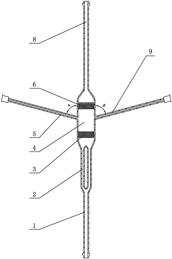
[0012]Specific implementation mode one: combine figure 1 Describe this embodiment, a decoupling reactor based on atmosphere switching in this embodiment includes a reaction tube main body, a thermocouple side tube 5 and an instantaneous feed side tube 9, and the reaction tube main body is divided into a lower part from bottom to top Pipe section 1, lower annulus section 2, lower porous plate 3, reaction section 4, upper porous plate 6, upper pipe section 8, thermocouple side pipe 5 and instantaneous feed side pipe 9 are arranged on both sides of reaction section 4, and thermoelectric One end of the double side pipe 5 is connected with the outer wall of the reaction section 4, and one end of the instantaneous feed side pipe 9 is connected with the outer wall of the reaction section 4; The outer diameter of the annulus is 8 mm to 12 mm, the width of the annulus is 1 mm to 2 mm, and the height of the annulus is 50 mm to 100 mm; the material of the main body of the reaction tube i...
specific Embodiment approach 2
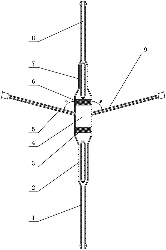
[0015] Specific implementation mode two: combination figure 2 To illustrate this embodiment, the lower end of the upper pipe section 8 of a decoupling reactor based on atmosphere switching described in this embodiment is provided with an upper annulus segment 7; the airflow channel in the upper annulus segment 7 is an annular gap, The outer diameter of the annular gap is 8 mm to 12 mm, the width of the annular gap is 1 mm to 2 mm, and the height of the annular gap is 50 mm to 150 mm.
[0016] The technical effect of this embodiment is: such arrangement can make the reactor more versatile and more flexible in use; the airflow can enter the reactor from the lower pipe section 1 and flow upward, and the reactor can be used as a fluidized bed or a fixed bed; The upper pipe section 8 enters the reactor and flows downward; when the gas flow flows downward, the upper annulus section 7 can fully preheat the gas flow, and the reactor is used as a fixed bed at this time. Other compone...
specific Embodiment approach 3
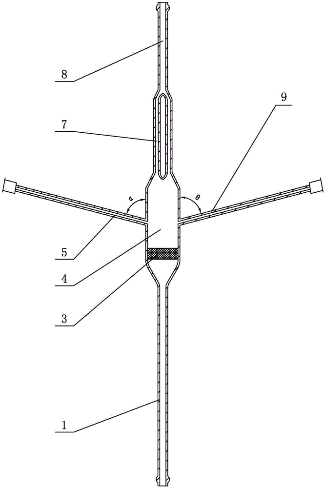
[0017] Specific implementation mode three: combination image 3 Describe this embodiment, a decoupling reactor based on atmosphere switching in this embodiment includes a reaction tube main body, a thermocouple side tube 5 and an instantaneous feed side tube 9, and the reaction tube main body is divided into a lower part from bottom to top Pipe section 1, lower perforated plate 3, reaction section 4, upper annulus section 7 and upper pipe section 8, thermocouple side pipe 5 and instantaneous feed side pipe 9 are arranged on both sides of reaction section 4, and thermocouple side pipe 5 One end is connected with the outer wall of the reaction section 4, and one end of the instantaneous feed side pipe 9 is connected with the outer wall of the reaction section 4; the air flow channel in the upper annular gap section 7 is an annular gap, and the outer diameter of the annular gap is 8mm ~12mm, the width of the annulus is 1mm~2mm, the height of the annulus is 50mm~150mm; the materia...
PUM
| Property | Measurement | Unit |
|---|---|---|
| width | aaaaa | aaaaa |
| height | aaaaa | aaaaa |
| height | aaaaa | aaaaa |
Abstract
Description
Claims
Application Information
 - R&D
- Intellectual Property
- Life Sciences
- Materials
- Tech Scout
- Unparalleled Data Quality
- Higher Quality Content
- 60% Fewer Hallucinations
Browse by: Latest US Patents, China's latest patents, Technical Efficacy Thesaurus, Application Domain, Technology Topic, Popular Technical Reports.
© 2025 PatSnap. All rights reserved.Legal|Privacy policy|Modern Slavery Act Transparency Statement|Sitemap|About US| Contact US: help@patsnap.com