
A DC Traction Power Supply System Based on Flexible DC Transmission

A flexible DC transmission and DC traction technology, applied in electric traction, DC circuits can reduce harmonics/ripples, electric vehicles, etc., can solve the problem of rectifier units increasing the complexity of traction substations and affecting the reliability of DC traction power supply systems In order to achieve the effects of small ripple, lower harmonic content, and reduced voltage and power loss

Active Publication Date: 2015-09-23
ZHUZHOU NAT ENG RES CENT OF CONVERTERS
View PDF2 Cites 0 Cited by
  • Summary
  • Abstract
  • Description
  • Claims
  • Application Information

AI Technical Summary

Problems solved by technology

[0004] In the dual-standard traction power supply system for electric locomotives and urban rail vehicles proposed by some practitioners, an AC backup 10kV power supply is used to establish a DC traction station required for subway / light rail locomotives; however, the existence of rectifier units increases the complexity of the traction substation. Device output characteristics affect reliability of DC traction power supply system
In addition, the rated voltage of the DC traction motor cannot be too high due to the commutation conditions, that is, the voltage of the traction network is difficult to further increase, which requires the traction network to transmit a large amount of current to supply urban rail vehicles, which will be limited by the capacity of the backup power supply

Method used


Image

  • A DC Traction Power Supply System Based on Flexible DC Transmission
  • A DC Traction Power Supply System Based on Flexible DC Transmission

Examples


Embodiment Construction

[0018] The present invention will be further described in detail below in conjunction with the accompanying drawings and specific embodiments.

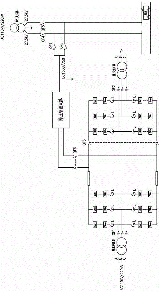
[0019] Such as figure 1 As shown, a DC traction power supply system based on flexible DC transmission of the present invention includes a step-down transformer, a double-terminal active high-voltage DC transmission system and a step-down chopper circuit. The double-ended active HVDC power transmission system includes two fully symmetrical converters, each of which is connected to the three-phase AC through a step-down transformer; the input end of the step-down chopper circuit is connected to the double-ended active The source is connected to the DC side of the high-voltage direct current transmission system, and the output end is connected to the traction system through the second switch assembly; the second switch assembly is interlocked with the third switch assembly.

[0020] see figure 1 , the first switch component is QF6, the...


PUM


Abstract

The invention discloses a direct current tractive power supply system based on flexible direct current power transmission. The direct current tractive power supply system comprises a step-down transformer, a double-end active high-voltage direct current power transmission system and a buck chopper. The double-end active high-voltage direct current power transmission system is based on the modularized multi-level converter technology and comprises two converters which are completely symmetric and connected through a direct current power transmission cable. Each converter is connected with the three-phase alternating current through the step-down transformer. The input end of the buck chopper is connected with the direct current side of the double-end active high-voltage direct current power transmission system through a first switch assembly, and the output end of the buck chopper is connected with a traction system through a second switch assembly. The second switch assembly is interlocked with a third switch assembly, when a metro or a light rail operates, the second switch assembly is switched on, the third switch assembly is switched off, and when an electric locomotive operates, the third switch assembly is switched on, and the second switch assembly is switched off. The direct current tractive power supply system has the advantages of being low in cost, little in traction network voltage and electric energy loss, low in harmonic content, high in system power coefficient, wide in application range and the like.

Description

technical field [0001] The invention mainly relates to the power supply field of electric traction technology, in particular to a DC traction power supply system based on flexible DC transmission. Background technique [0002] Electrified railway traction power supply system is a complete set of devices specially used to supply electric energy to electric locomotives or EMUs on railways that use electric locomotives as traction power. The electric energy used by my country's electrified railways is supplied by the power plants of the national power department. In order to reduce the loss of electric energy in the process of power transmission, the voltage is raised to 110 kV or 220 kV (it is developing towards 500 kV ultra-high voltage power transmission). Then it is sent to the traction substation through the transmission line. The traction substation is generally located near the station, which is mainly used to transform the high-voltage three-phase alternating current se...

Claims


Application Information

Patent Timeline
Patent Type & Authority Patents(China)
IPC IPC(8): H02J1/02H02J3/36B60L9/00
CPCY02T10/7241Y02T10/72
Inventor 王卫安龚芬周方圆黄燕艳吴强罗仁俊曹洋张定华龙礼兰王才孝邓明张典吴选保胡前
Owner ZHUZHOU NAT ENG RES CENT OF CONVERTERS
Learn More