
Middle layer joint connecting structure of concrete-filled steel tubular column and reinforced concrete beams

A technology for reinforced concrete beams and concrete-filled steel tube columns, which is applied in the field of connection structures between concrete-filled steel tube columns and mid-level nodes of reinforced concrete beams. Effect

Inactive Publication Date: 2014-07-02
CHINA RAILWAY SIYUAN SURVEY & DESIGN GRP
View PDF0 Cites 4 Cited by
  • Summary
  • Abstract
  • Description
  • Claims
  • Application Information

AI Technical Summary

Problems solved by technology

However, the structure of CFST column joints is complex and various, and there is still no set of widely applicable structural forms and corresponding calculation methods in China to meet the needs of the development of CFST structures.

Method used


Image

  • Middle layer joint connecting structure of concrete-filled steel tubular column and reinforced concrete beams
  • Middle layer joint connecting structure of concrete-filled steel tubular column and reinforced concrete beams
  • Middle layer joint connecting structure of concrete-filled steel tubular column and reinforced concrete beams

Examples


Embodiment Construction

[0020] The present invention will be further described in detail below in conjunction with the accompanying drawings and specific embodiments to facilitate a clear understanding of the present invention, but they do not limit the present invention.

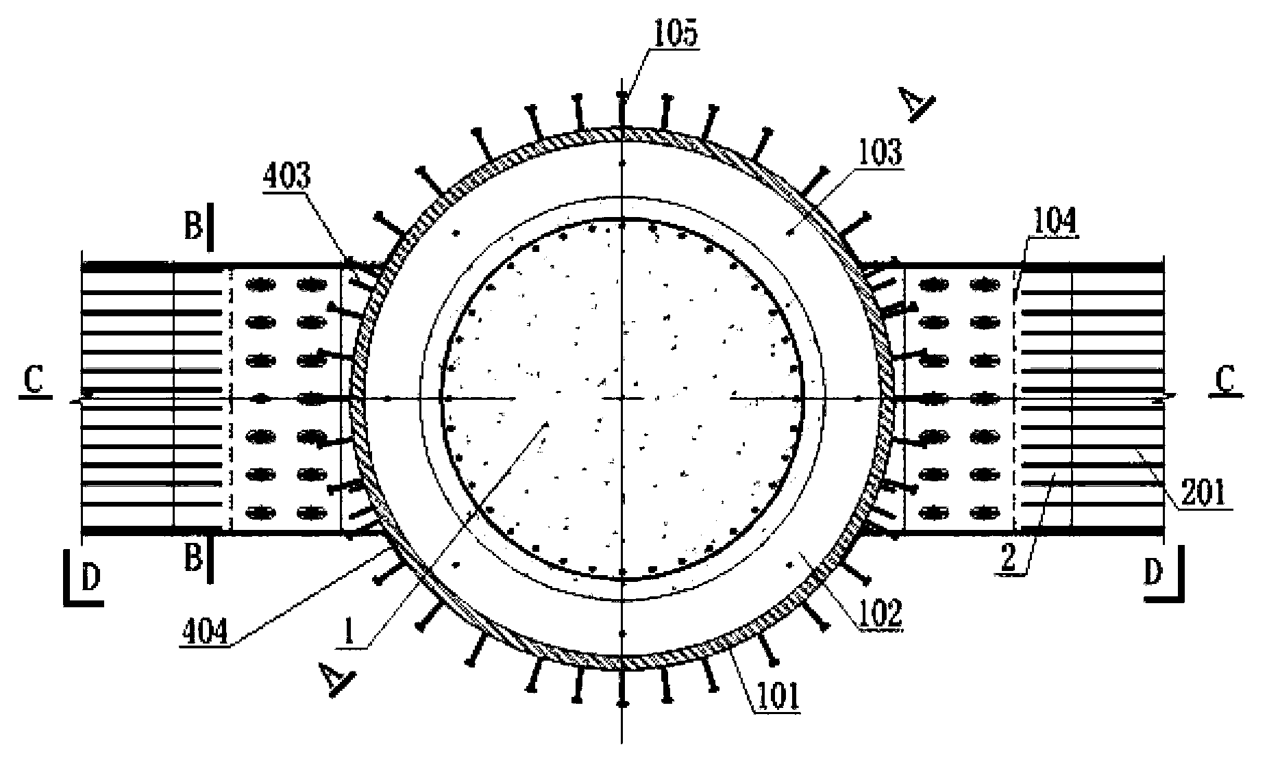
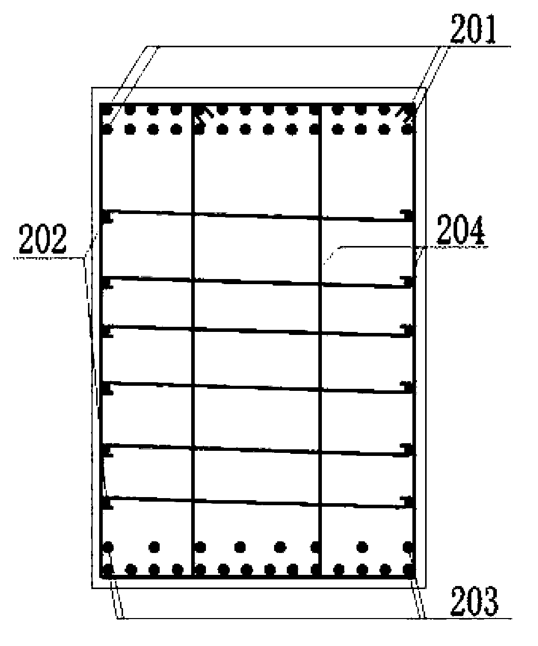
[0021] Such as figure 1 As shown, the present invention comprises a steel pipe concrete column 1 and a reinforced concrete beam 2 connected thereto, and the plain concrete area at the junction of the reinforced concrete beam 2 and the steel pipe concrete column 1 is provided with node shear reinforcement, and the node shear reinforcement connects the node The area concrete forms a concrete ring to the overall structure.

[0022] Such as figure 2 As shown, the steel pipe concrete column 1 includes a steel pipe 101, and a hoop stiffening plate 102 is arranged inside the steel pipe 101, and a concrete pouring hole 103 is opened on the hoop stiffening plate 102, and a vertical Stiffeners 106 , column end transition plates 104 are a...


PUM


Abstract

The invention relates to the field of structural engineering technologies, in particular to a middle layer joint connecting structure of a concrete-filled steel tubular column and reinforced concrete beams. The middle layer joint connecting structure comprises the concrete-filled steel tubular column and the reinforced concrete beams connected with the concrete-filled steel tubular column. The concrete-filled steel tubular column comprises a steel tube, an annular stiffening plate and vertical stiffening ribs are arranged in the steel tube, column end transition plates are arranged outside the steel tube and connected with upper main reinforcement connecting plates on the upper portions of the reinforced concrete beams and lower main reinforcement connecting plates on the lower portions of the reinforced concrete beams through high-strength bolts, and joint shear reinforcements are arranged at the connecting position between every two adjacent reinforced concrete beams. Connecting joints between the concrete-filled steel tubular column and the reinforced concrete beams are connected through high-strength bolts, concrete is cast, so that stress and plastic deformation capacity of a beam column are improved, the on-site welding quantity is small, construction is easy, and the middle layer joint connecting structure has the advantages of being good in ductility, easy and convenient to manufacture and install and convenient to repair after an earthquake and has good application prospects in the fields of large-scale public buildings and others.

Description

technical field [0001] The invention relates to the technical field of structural engineering, in particular to a joint connection structure between a steel pipe concrete column and a reinforced concrete beam mid-level node. Background technique [0002] In the prior art, the connection nodes between the steel pipe concrete columns and the reinforced concrete beams are relatively mature. At present, there are many engineering examples in China that use steel pipe concrete columns to connect reinforced concrete beams or steel beams: the ring-shaped corbel welded on the steel pipe column is welded to the main reinforcement of the reinforced concrete beam, or the connecting plate welded on the steel pipe column Direct welding with the main reinforcement of reinforced concrete beams, etc. [0003] The ring-shaped corbels or connecting plates welded on the above-mentioned steel pipe columns are directly connected to the main bars of the reinforced concrete beams. Although the st...

Claims


Application Information

Patent Timeline
Patent Type & Authority Applications(China)
IPC IPC(8): E04B1/58
Inventor 周小华雷崇王金平沈婷罗会平朱炎兵王永伟
Owner CHINA RAILWAY SIYUAN SURVEY & DESIGN GRP
Learn More