
Zig-zag derrick for replacing disconnecting link

A technology of herringbone poles and herringbone poles is applied in the directions of transportation and packaging, load hanging components, etc., which can solve the problems of many difficulties in the construction process, difficult control of safety technical and economic indicators, and large hidden dangers, etc. Easy to disassemble, easy to carry and assemble, safe and controllable

Inactive Publication Date: 2014-07-02
STATE GRID CORP OF CHINA +2
View PDF10 Cites 2 Cited by
  • Summary
  • Abstract
  • Description
  • Claims
  • Application Information

AI Technical Summary

Problems solved by technology

[0004] 1. Self-made processing, iron steel pipe holding pole, no reliable safety factor, no test for lifting load, relatively high risk and hidden danger
2. The entire 6.5-meter-long pole is inconvenient to carry and must be transported by a large vehicle
3. The 6.5-meter steel pipe holding pole has a large turning radius and limited upper and lower space in the operating substation, which poses a greater safety risk to the operation of the equipment
4. There are 12 people involved in the construction work, the labor intensity of the personnel is high, it is easy to damage the knife gate porcelain bottle, and the construction method is cumbersome
5. The construction efficiency is low, the construction process is difficult, there are many risk factors for personal safety and equipment safety, and the safety technical and economic indicators are difficult to control

Method used


Image

  • Zig-zag derrick for replacing disconnecting link
  • Zig-zag derrick for replacing disconnecting link

Examples


Embodiment Construction

[0020] In order to make the content of the present invention more obvious and understandable, the following in conjunction with the attached Figure 1-Figure 2 and specific implementation methods for further description.

[0021] In order to make the object, technical solution and advantages of the present invention clearer, the present invention will be further described in detail below in conjunction with the accompanying drawings and embodiments. It should be understood that the specific embodiments described here are only used to explain the present invention, not to limit the present invention.

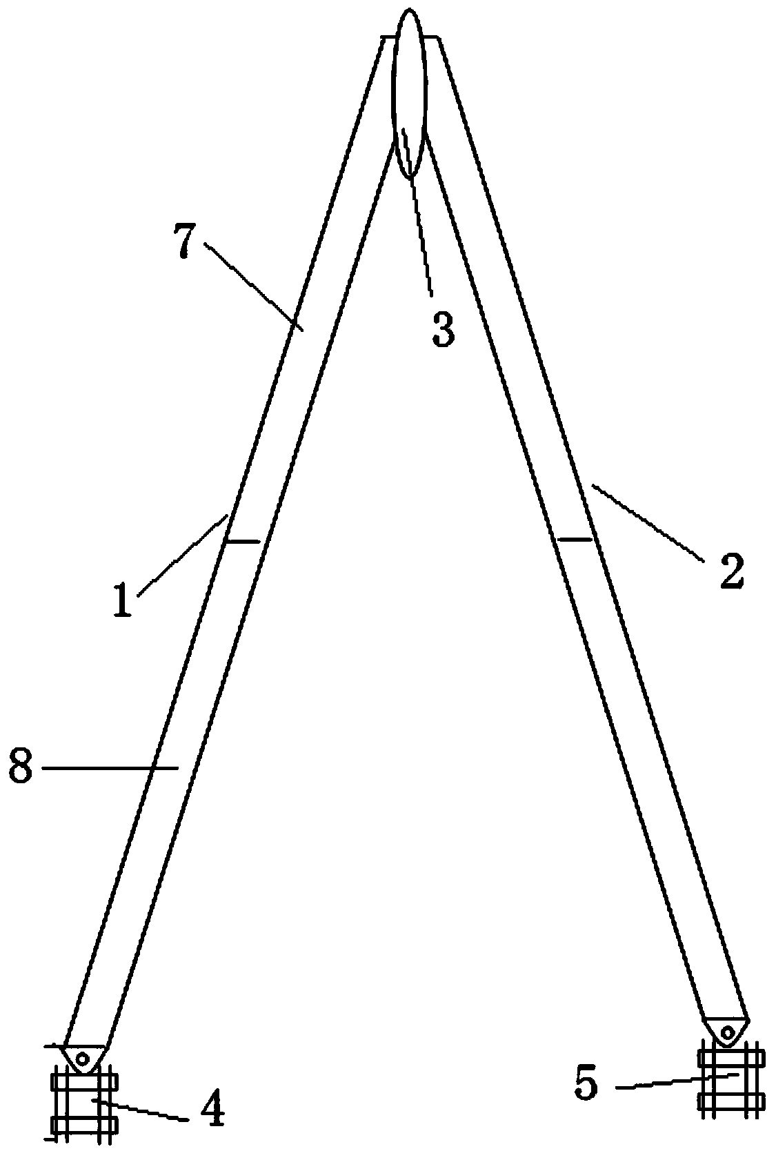
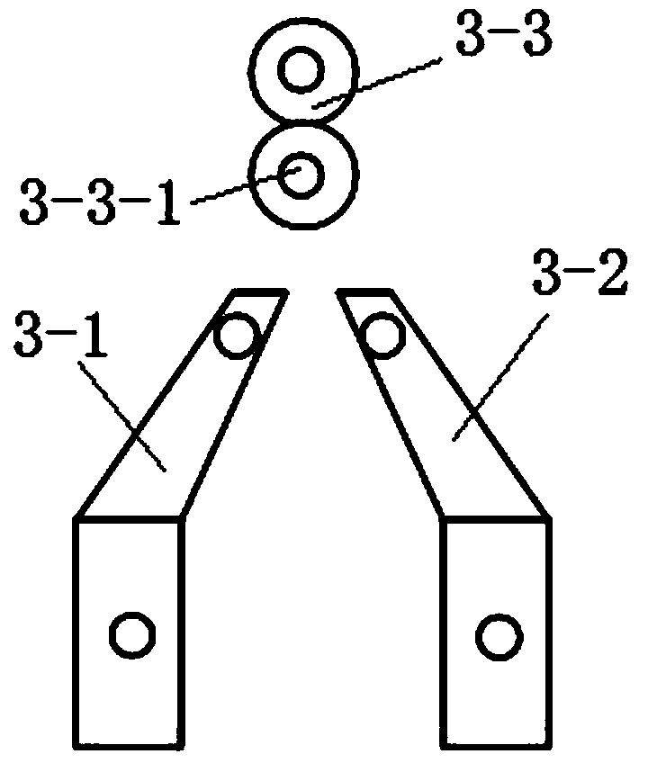
[0022] A herringbone holding rod for replacing a knife switch, comprising a left herringbone rod 7, a right herringbone rod 8, a suspension head 3, a left fixing seat 4 and a right fixing seat 5;

[0023] The left herringbone 7 and the right herringbone 8 include an upper column 1 and a lower column 2;

[0024] Suspension head 3 comprises left connecting plate 3-1, right connec...


PUM


Abstract

The invention discloses a zig-zag derrick for replacing a disconnecting link. The to-be-solved technical problem is that a derrick adopted in an existing central plain running substation disconnecting link replacement construction method has defects in background technology. The adopted technical scheme is that the zig-zag derrick for replacing the disconnecting link comprises a left zig-zag rod, a right zig-zag rod, a suspending head, a left fixed seat and a right fixed seat; the suspending head is connected with upper ends of the left zig-zag rod and the right zig-zag rod; the left zig-zag rod and the right zig-zag rod are 'zig-zag'; the left fixed seat is arranged on the bottom end of the left zig-zag rod; the right fixed seat is arranged on the bottom end of the right zig-zag rod; the left zig-zag rod and the right zig-zag rod both comprise upper vertical columns and lower vertical columns; the upper vertical columns and the lower vertical columns are detachably connected; the suspending head comprises a left connecting plate, a right connecting plate and a lifting hook; the lower end of the left connecting plate is connected with the top end of the right zig-zag rod; the lower end of the right connecting plate is connected with the top end of the right zig-zag rod; the upper end of the left connecting plate and the upper end of the right connecting plate are connected with the lifting hook synchronously; the lifting hook is provided with a through hole.

Description

technical field [0001] The invention relates to a herringbone holding rod for replacing a knife switch, in particular to a herringbone holding rod for replacing or newly installing a 110KV and 35KV knife switch, which belongs to the configuration of lifting tools. Background technique [0002] The construction method of replacing the knife switch in the original operating substation, 220kV, 110kV knife switch group, the new installation adopts a Ф10 cm ordinary steel pipe holding pole, 6.5 meters long, cannot be segmented, transported by large vehicles, enters the operating substation and lifts to the 2nd floor platform, extended Use the lifting process to ensure that the interval space satisfies the safe distance to hold the pole and lift it into the air. 12 people cooperate with the operation at the same time, and the command is unified. 3 people stabilize the root of the pole, and 4 people control the direction of the wind rope. The holding pole was moved to the root of t...

Claims


Application Information

Patent Timeline
IPC IPC(8): B66C13/00
Inventor 裴有慧韩舒程建国杨俊杨建吴鹏夏添曹广瑞
Owner STATE GRID CORP OF CHINA
Learn More