Tool for die machining

A mold processing and cutting tool technology, which is applied in the direction of lathe cutting tools, metal processing equipment, manufacturing tools, etc., can solve the problems of affecting mold quality, mold scrapping, spring knife overcutting, etc., and achieve simple structure and reduce spring knife overcutting. The effect of cutting and increasing thickness

Inactive Publication Date: 2014-07-02
中山市利群精密实业有限公司
View PDF6 Cites 0 Cited by
  • Summary
  • Abstract
  • Description
  • Claims
  • Application Information

AI Technical Summary

Problems solved by technology

[0002] In the process of mold processing, it often occurs that the knife bounces at the corner and causes overcutting
This will affect the quality of the part of the mold, or even scrap the entire mold, causing serious losses

Method used


Image

  • Tool for die machining

Examples


Embodiment Construction

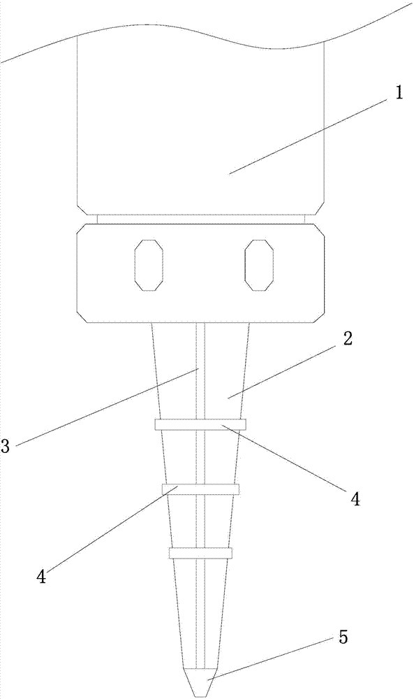
[0012] The present invention will be further described below in conjunction with accompanying drawing description and specific embodiment:

[0013] like figure 1 The shown tool for mold processing includes a knife handle connected to the tool mounting seat 1, a knife edge portion 2 is provided on one end of the knife handle, and a knife edge portion 2 is provided in the axial direction The reinforcing rib 3 is provided with a reinforcing convex ring 4 along the radial direction on the outer wall of the blade portion 2 .

[0014] There are three reinforcing ribs 3 in the present invention, which are evenly distributed on the outer wall of the blade part 2 respectively.

[0015] There are three reinforcing protruding rings 4 in the present invention, and the three reinforcing protruding rings 4 are arranged on the outer wall of the blade part 2 at intervals.

[0016] In the present invention, a blade 5 is provided at the front end of the blade portion 2 .

[0017] The present...


PUM


Abstract

The invention discloses a tool for die machining. The tool comprises a tool handle connected to a tool mounting base. One end of the tool handle is provided with a blade part. The tool is characterized in that the blade part is provided with a reinforcing rib in the axial direction, and a reinforcing protruding ring is arranged in the radial direction of the outer wall of the blade part. The shortcomings in the prior art are overcome, the tool for die machining is simple in structure, and tool high vibration and excessive cutting can be effectively avoided.

Description

technical field [0001] The invention relates to a cutting tool for mold processing. Background technique [0002] In the process of mold processing, it often happens that the knife bounces at the corner and causes overcutting. This will affect the quality of the mold part, and even make the whole mold scrapped, causing serious losses. Contents of the invention [0003] The object of the present invention is to overcome the disadvantages of the prior art and provide a tool for mold processing which has a simple structure and can effectively prevent overcutting of the bulletproof knife. [0004] In order to achieve the above object, the present invention adopts the following scheme: [0005] A tool for mold processing, comprising a tool handle connected to a tool mounting seat, a knife edge is provided at one end of the tool handle, and it is characterized in that: a reinforcing rib is arranged on the knife edge along the axial direction , a reinforcing convex ring is arr...

Claims


Application Information

Patent Timeline
Patent Type & Authority Applications(China)
IPC IPC(8): B23B27/02
CPCB23B27/02
Inventor 童章狄
Owner 中山市利群精密实业有限公司
Why Eureka
Try Eureka