Electricity storage device control system

A technology of management system and power storage device, applied in the direction of circuit devices, battery circuit devices, circuits, etc.

Active Publication Date: 2014-06-25
TOSHIBA MITSUBISHI-ELECTRIC IND SYST CORP
View PDF9 Cites 1 Cited by
  • Summary
  • Abstract
  • Description
  • Claims
  • Application Information

AI Technical Summary

Problems solved by technology

In addition, in the power storage device disclosed in Patent Document 2, the charging current can be reliably blocked in a state where the temperature of the battery is raised due to rapid charging of a large current.

Method used


Image

  • Electricity storage device control system
  • Electricity storage device control system
  • Electricity storage device control system

Examples


Embodiment approach 1

[0031] In the present embodiment, all the electric storage cells constituting each electric storage system are storage batteries such as lithium ion batteries. Therefore, in the present embodiment, the electric storage unit will be described as a storage battery.

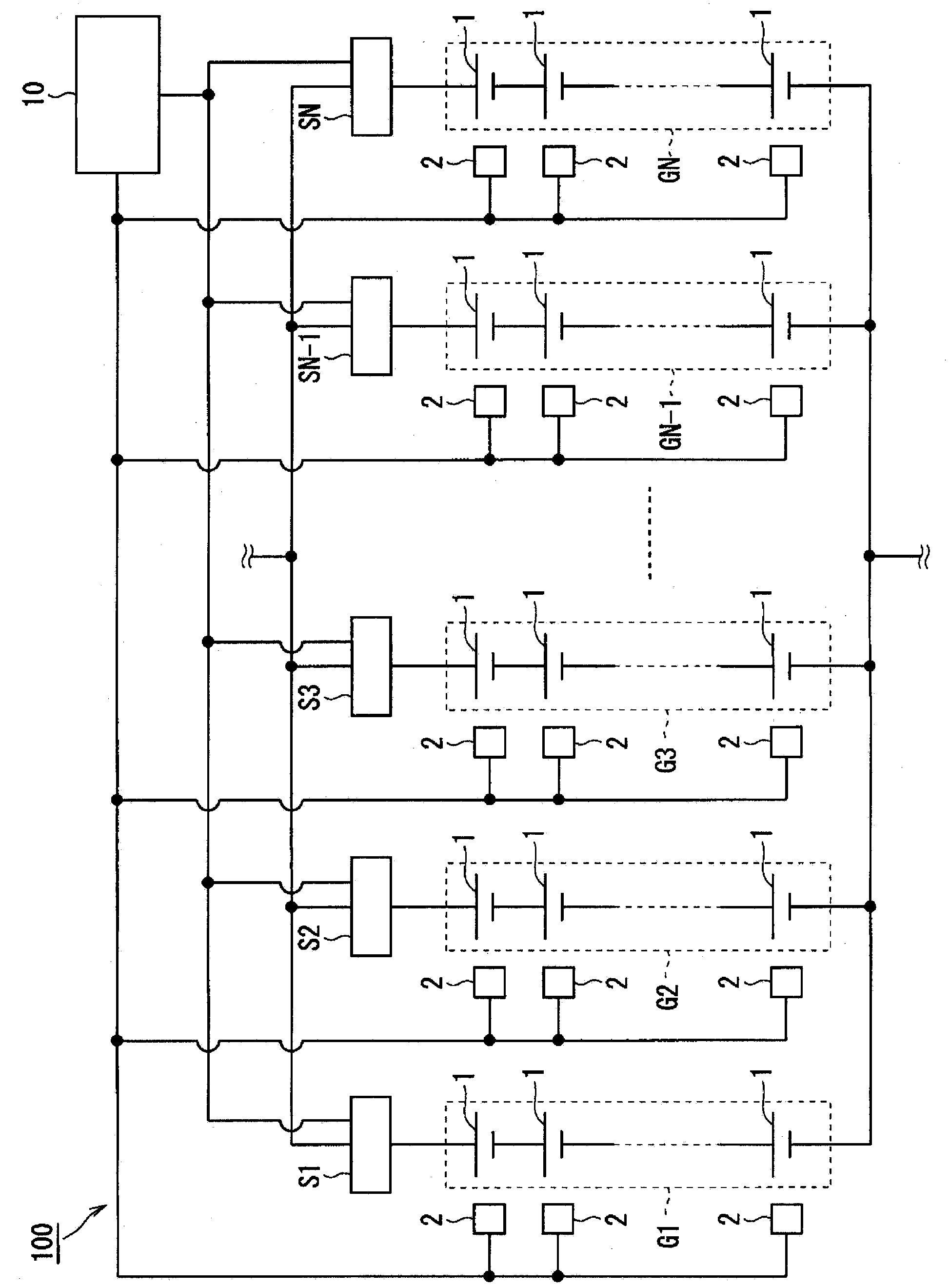
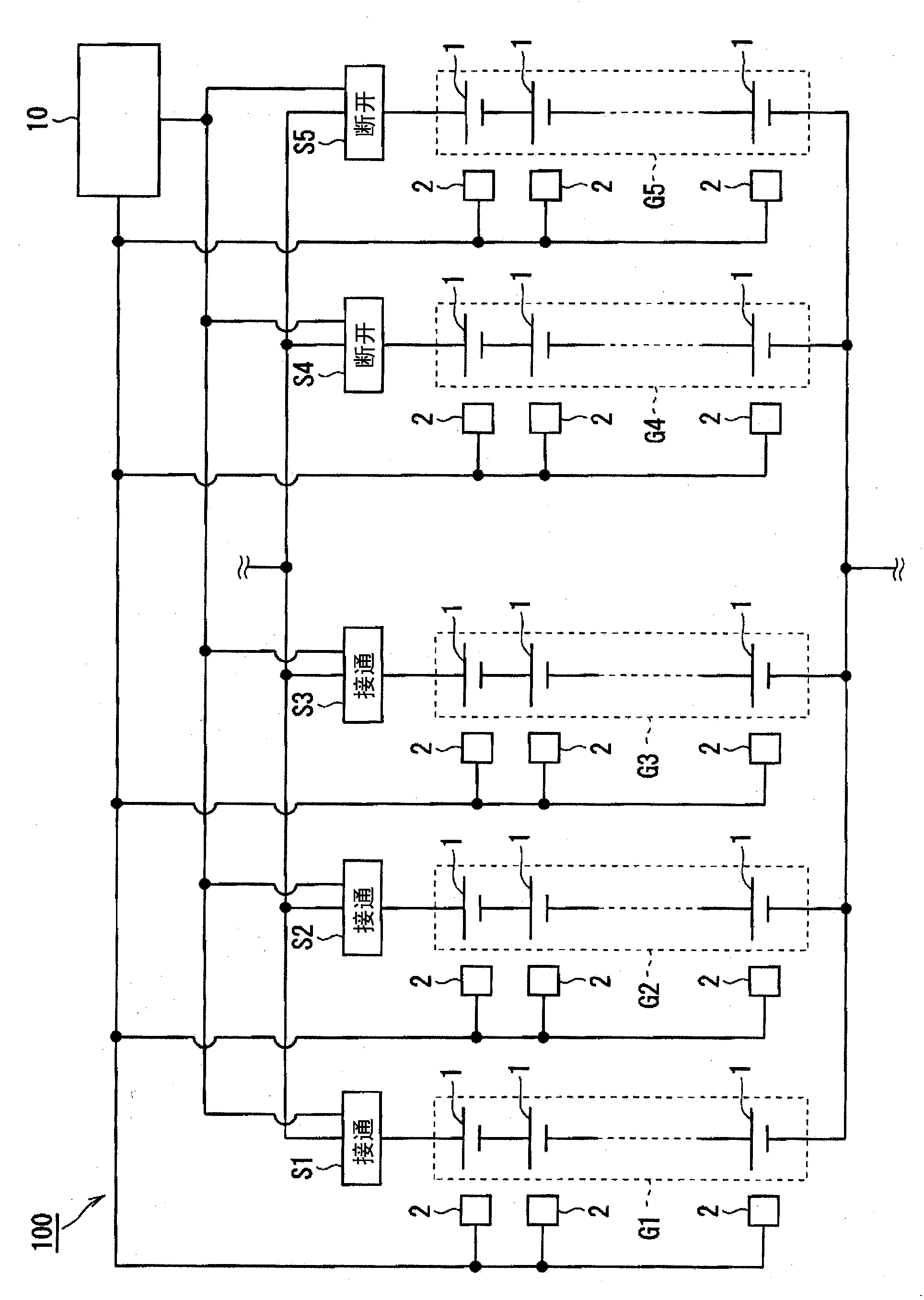
[0032] figure 1 is a diagram showing the configuration of the power storage device management system 100 according to the present embodiment. Here, it can be understood that in figure 1 The configuration other than the control unit 10 is an electric storage device. The power storage device management system 100 includes a power storage device and a control unit 10 that monitors and controls the power storage device.

[0033] In case of discharge, figure 1 A portion of the illustrated power storage device indicated by broken lines is connected to a load such as electronic / electric equipment via a converter or the like, and the power storage device functions as a power source for the load. Also in the case of cha...


PUM


Abstract

The purpose of the present invention is to provide an electricity storage device control system capable of acquiring high input and output during charging and discharging of the electricity storage device continuously for a long time. In an electricity storage device control system (100) according to the present invention, a control unit (10) monitors the temperature of each electricity storage cell (1). When the temperature of any electricity storage cell (1) in an electricity storage system (G1-G5) reaches a first threshold temperature during the charging and discharging operation, the control unit (10) switches the electricity storage system (G1-G5) including the electricity storage cell (1) to a state where the charging and discharging is suspended. Further, the control unit (10) switches the electricity storage system (G1-G5) from the suspended state to the state of charging and discharging operation.

Description

technical field [0001] The present invention relates to a storage battery management system that performs control during charging and discharging operations of an electrical storage device including an electrical storage unit such as a lithium ion battery. Background technique [0002] The development of secondary batteries continues to progress, and lithium-ion batteries, for example, have high capacity and high energy density, and are easy to realize miniaturization and weight reduction, and are attracting attention. [0003] In addition, power storage devices used as power sources for various electronic / electric devices are generally configured by connecting a plurality of secondary batteries in series and in parallel. When using the power storage device as a power source, the power storage device is connected to electronic / electric equipment and discharged. Also, when charging the power storage device, the power storage device is connected to the power supply system. ...

Claims


Application Information

Patent Timeline
Patent Type & Authority Applications(China)
IPC IPC(8): H02J7/04H02J7/00H02J7/02
CPCH02J7/0026H02J7/02H02J7/04H02J7/00H02J7/0032H02J7/0014Y02E60/10H02J7/007194H02J5/00H01M10/441H02J7/00309
Inventor 花田雅人
Owner TOSHIBA MITSUBISHI-ELECTRIC IND SYST CORP
Why Eureka
Try Eureka