Method for adjusting exposure time of camera

A technology of exposure time and adjustment method, applied in the field of intelligent transportation, can solve the problems of inability to adjust brightness and poor exposure effect, and achieve the effect of avoiding gray value changes and accurate exposure time.

Active Publication Date: 2014-06-25
UNIV OF SCI & TECH OF CHINA
View PDF4 Cites 30 Cited by
  • Summary
  • Abstract
  • Description
  • Claims
  • Application Information

AI Technical Summary

Problems solved by technology

[0010] Due to the automatic exposure control method based on the average value of image brightness in the prior art, the exposure effect of the scene under the conditions of backlight and strong frontal light is not good in the traditional average algorithm
Although the automatic exposure control method based on the image brightness histogram overcomes the shortcomings of the traditional average method in the case of backlight and strong front light to a certain extent, it still cannot perform targeted brightness adjustment for the content of interest in the image.

Method used


Image

  • Method for adjusting exposure time of camera
  • Method for adjusting exposure time of camera
  • Method for adjusting exposure time of camera

Examples


Embodiment 1

[0024] figure 1 It is a flow chart of a method for adjusting the exposure time of a camera provided by Embodiment 1 of the present invention. Such as figure 1 As shown, the method mainly includes the following steps:

[0025] Step 11. Determine the region of interest in the current frame image according to the position of the driver's nose in the previous frame image, and calculate the brightness feature estimation value in the region of interest.

[0026] In the embodiment of the present invention, the determination of the brightness of the image needs to calculate the gray value of a specific area, so it is necessary to select a suitable area in the image for calculation, and this area is called the area of ​​interest. In addition, the scene in the car is relatively complex. In addition to the brightness change of the scene, the change of the driver's driving posture will also cause the change of the gray value in the selected area. Therefore, the position of the region o...

Embodiment 2

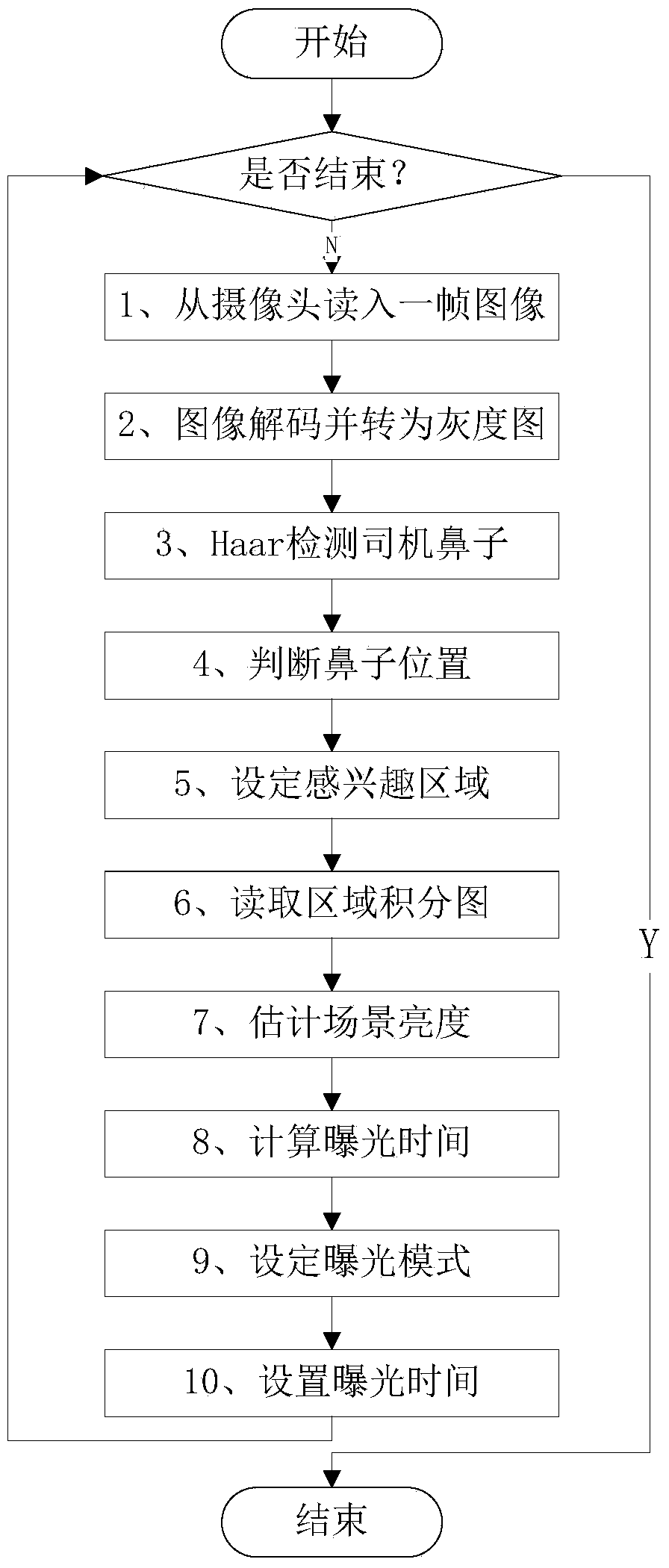
[0071] In order to facilitate understanding of the present invention, below in conjunction with Figure 2-3 for further clarification.

[0072] Such as figure 2 As shown, it is a flowchart of a method for adjusting the exposure time of a camera provided by the present invention, which mainly includes:

[0073] 1) Read in images from a USB camera.

[0074] 2) Decode the read image into an RGB three-channel image, and then convert it into a grayscale image.

[0075] 3) Use the trained Haar classifier to detect the driver's nose, mainly including: calculating the integral map of the region of interest, calculating the Haar feature according to the integral map, and then using the classifier to detect the position of the nose.

[0076] 4) Determine whether the detected nose position is near the reference position.

[0077] 5) According to the detected nose position, expand the nose area outward as the region of interest.

[0078] 6) Read the integral image during Haar detect...


PUM


Abstract

The invention discloses a method for adjusting the exposure time of a camera. The method comprises the steps that an interested area is determined according to the position of the nose of a driver in a detected current frame image, and the estimated value of the brightness feature in the interested area is calculated; the estimated value of the brightness feature and the exposure time set value of a current frame of the camera are compared to obtain the difference value of the estimated value of the brightness feature and the exposure time set value; the exposure time set value of the next frame of the camera is calculated according to the difference value, and the exposure time of the next frame of the camera is adjusted according to the exposure time set value. Through the method for adjusting the exposure time of the camera, the brightness variation of images can be quickly and accurately judged according to indexes, and therefore the exposure time of the camera can be accurately calculated.

Description

technical field [0001] The invention relates to the technical field of intelligent transportation, in particular to a method for adjusting the exposure time of a camera. Background technique [0002] With the rapid development of my country's economy, the number of residents' car ownership has also continued to increase. According to statistics, by the end of 2011, the number of automobiles in my country exceeded 100 million, and the number of motor vehicle drivers reached 230 million. However, in recent years, traffic accidents are also on the rise, bringing more and more serious losses to the national economy and people's lives and property. The problem of traffic safety is becoming more and more serious, and has received more and more attention. According to investigations, human factors are the main cause of traffic accidents. According to incomplete statistics, the number of deaths caused by road traffic accidents in the world exceeds 800,000. In my country, there w...

Claims


Application Information

Patent Timeline
IPC IPC(8): H04N5/235G06K9/46
Inventor 凌强李佳桐李峰邓思斌
Owner UNIV OF SCI & TECH OF CHINA
Why Eureka
Try Eureka