
Electric system phasor calculating method suitable for frequency deviation

A power system and calculation method technology, which is applied in frequency measurement devices, measurement of electrical variables, and frequency-to-amplitude conversion. It can solve the problems of troublesome correction, sacrifice of measurement accuracy, and large amount of calculation, etc., and achieve small memory usage and fast calculation speed. , high precision effect

Inactive Publication Date: 2014-06-25
SHANDONG UNIV
View PDF6 Cites 6 Cited by
  • Summary
  • Abstract
  • Description
  • Claims
  • Application Information

AI Technical Summary

Problems solved by technology

However, the current phasor algorithm either makes the correction after Fourier transform very troublesome and requires a lot of calculation in order to meet the accuracy; or sacrifices the measurement accuracy in order to meet the calculation speed
At present, there is still no suitable algorithm that can meet the actual phasor measurement accuracy on the basis of taking into account the calculation cost, and is suitable for severe frequency offset and various system operation modes

Method used


Image

  • Electric system phasor calculating method suitable for frequency deviation
  • Electric system phasor calculating method suitable for frequency deviation
  • Electric system phasor calculating method suitable for frequency deviation

Examples


Embodiment 1

[0050] Assume that the sequence of single-phase sampled values ​​after low-pass filtering is expressed as X(i)=1.34*cos(2*f*π*i*0.00025), i=0, 1, 2, 3, . . . . N is taken as 80, that is, 80 sampling points per cycle, and the sampling interval is T S =0.00025 seconds. Unless otherwise specified, the calculation variable is of double type, the unit of phase is angle, the unit of frequency is Hz, and decimal truncation is rounded off.

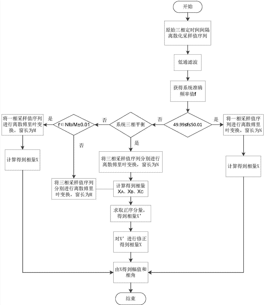
[0051] Assume that the current system is in a three-phase balanced state, the system frequency is 47Hz, and the current sampling time is (100×T S ), then when f=47Hz, the nearest integral frequency range to this frequency is: M=85, 47Hz is out of the whole point frequency range. According to the algorithm rules, choose step three.

[0052] X(i) A =1.34*cos(2*f*π*i*0.00025)

[0053] X ( i ) B = 1.34 * cos ...

Embodiment 2

[0059] Assume that the sequence of single-phase sampled values ​​after low-pass filtering is expressed as X(i)=1.34*cos(2*f*π*i*0.00025), i=0, 1, 2, 3, . . . . N is taken as 80, that is, 80 sampling points per cycle, and the sampling interval is T S =0.00025 seconds. Unless otherwise specified, the calculation variable is of double type, the unit of phase is angle, the unit of frequency is Hz, and decimal truncation is rounded off.

[0060] Assuming that the current system is in a three-phase unbalanced state, there is a 5% negative sequence component, and the negative sequence leads the positive sequence by 30°. The system frequency is 47Hz, and the current sampling moment is (100×T S ).

[0061] Then when f=47Hz, the whole point frequency range closest to this frequency is: M=85, 47Hz is out of the whole point frequency range. According to the algorithm rules, choose step five.

[0062] X ( i ) ...

Embodiment 3

[0070] Assume that the sequence of single-phase sampled values ​​after low-pass filtering is expressed as X(i)=1.34*cos(2*f*π*i*0.00025), i=0, 1, 2, 3, . . . . N is taken as 80, that is, 80 sampling points per cycle, and the sampling interval is T S =0.00025 seconds. Unless otherwise specified, the calculation variable is of double type, the unit of phase is angle, the unit of frequency is Hz, and decimal truncation is rounded off.

[0071] Suppose the current system frequency is 50.01Hz, and the sampling time is (100×T S ), then when f=50.01Hz, according to the algorithm rules, choose step 2. Select the sampling window length as the default power frequency sampling points per cycle N=80.

[0072] X 100 = 2 80 Σ k = - 79 0 x 100 + ...


PUM


Abstract

The invention discloses an electric system phasor calculating method suitable for frequency deviation. The method comprises the step of carrying out synchronization fixed time interval discrete sampling is carried out on a three-phase signal, carrying out lowpass filtering on a sampling value sequence and carrying out real-time and accurate measurement on the system frequency to obtain the system frequency f, and the step of respectively selecting a fixed wavelength Fourier transform algorithm or a variable window length Fourier transform algorithm or a phaser correction positive sequence compensation algorithm or a variable window length positive sequence compensation algorithm according to different system states and different system frequency ranges to calculate the amplitude and the phase angle of the phasor. The electric system phasor calculating method has the advantages that only a period of sampling data need to be selected, the occupied internal storage is small, the three-phase data can be operated at the same time, the computing speed is high, precision is very high, the phase angle error is controlled within 0.1 degree, and the amplitude error is controlled within 0.1 percent. The electric system phasor calculating method is suitable for occasions on which the accurate frequency value can be obtained and the requirement for the phasor measuring precision and the computing speed are high, and the method meets the current measuring requirement for the phasor of a current smart power grid.

Description

technical field [0001] The invention belongs to the technical field of phasor measurement in electric power systems, and in particular relates to a high-precision phasor calculation method suitable for frequency deviation in electric power systems. Background technique [0002] Phasor in power system is an important observation quantity, which includes magnitude and phase. The power system safety automatic device should measure its value in real time, and make corresponding control measures according to the phasor changes of voltage and current. At present, PMUs are widely used in intelligent substations to measure the voltage and current phasors of the power system, and the calculation methods are almost all based on Fourier transform to calculate the amplitude and phase. Since the actual frequency of the power system fluctuates and cannot be kept at a power frequency of 50Hz continuously, the traditional phase-locking processing technology is no longer applicable to an A / ...

Claims


Application Information

Patent Timeline
Patent Type & Authority Applications(China)
IPC IPC(8): G01R25/00G01R23/06
Inventor 刘世明郭韬吴聚昆李建辉王仲哲肖迈
Owner SHANDONG UNIV
Learn More