Multipath linear isolation circuit and oscilloscope thereof

A linear isolation circuit, isolation circuit technology, applied in the direction of voltage/current isolation, instrumentation, measurement of electrical variables, etc., can solve the problems of low-frequency path circuit complexity, inability to function, delay compensation circuit ineffective, etc., to achieve winding Convenience, convenient debugging, simple frequency compensation circuit

Active Publication Date: 2014-06-25
RIGOL
View PDF6 Cites 9 Cited by
  • Summary
  • Abstract
  • Description
  • Claims
  • Application Information

AI Technical Summary

Problems solved by technology

[0012] 1. Since the secondary side of the transformer uses two windings, as the positive and negative poles of the output differential signal, it is difficult to ensure the same phase of the positive and negative poles, which increases the difficulty of transformer winding
[0013] 2. The linear optocoupler is used as the isolation of the low-frequency path. The delay of the low-frequency path causes the frequency response to be uneven. Circuits 48, 52, 50, and 54 are used to compensate. Because the capacitors are discrete, it is difficult to ensure that the positive and negative poles of the differential signal are completely unanimous
[0024] 2. The delay compensation circuit 103 or 22, 24, 29, 30 mentioned in the patent cannot actually solve the amplitude-frequency sag at the overlapping frequency of the low-frequency and high-frequency paths
Because the capacitors 24 and 30 play a low-pass role in the amplifier circuit shown, they can only make the high frequency of the low frequency path lower than the low frequency, but cannot properly increase the high frequency.
Circuit 103 is actually an RC low-pass circuit, which also cannot properly enhance high frequencies.
[0025] 3. Since the provided delay compensation circuit does not work, the output amplitude-frequency response of the linear isolation circuit is not flat
[0026] 4. The low-frequency path circuit is complex
[0027] To sum up, the main disadvantage of the existing technology is that the bandwidth of the linear isolation circuit that can be realized is low, and the isolation oscilloscope with a larger bandwidth cannot be realized.
Moreover, the frequency response depression problem caused by the linear optocoupler circuit

Method used


Image

  • Multipath linear isolation circuit and oscilloscope thereof
  • Multipath linear isolation circuit and oscilloscope thereof
  • Multipath linear isolation circuit and oscilloscope thereof

Examples


Embodiment 1

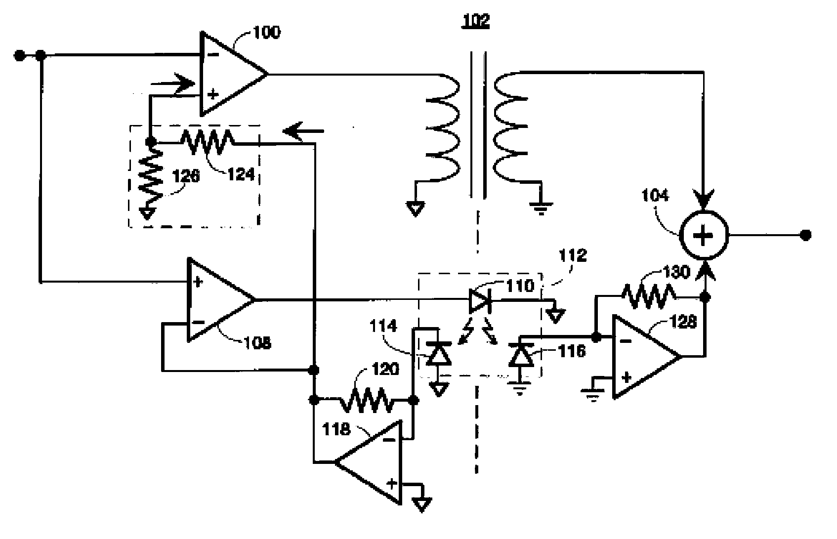
[0104] Figure 8 It is a schematic diagram of the structure of this embodiment. This embodiment is applicable to the application of single-ended signal input and single-ended signal output.

[0105] In this embodiment, the low-frequency amplifier circuit uses R and C low-pass filters, and an amplifier follower circuit. The resistance and capacitance determine the bandwidth of the low-frequency amplifier circuit, which needs to meet the bandwidth of the linear optocoupler circuit. The resistor is 10kΩ, the capacitor is 1.5nF, and the bandwidth of the low-frequency amplifier circuit is 10kHz. The amplifier can use any high-precision amplifier to meet the requirements for low-frequency sampling accuracy. Of course, the selection of better amplifiers such as precision, low noise, low distortion, low bias current, and low-temperature drift can be beneficial to the low-frequency high-precision technical effect. accomplish. For example, choose AD823 and AD8639 of ADI Company.

[...

Embodiment 2

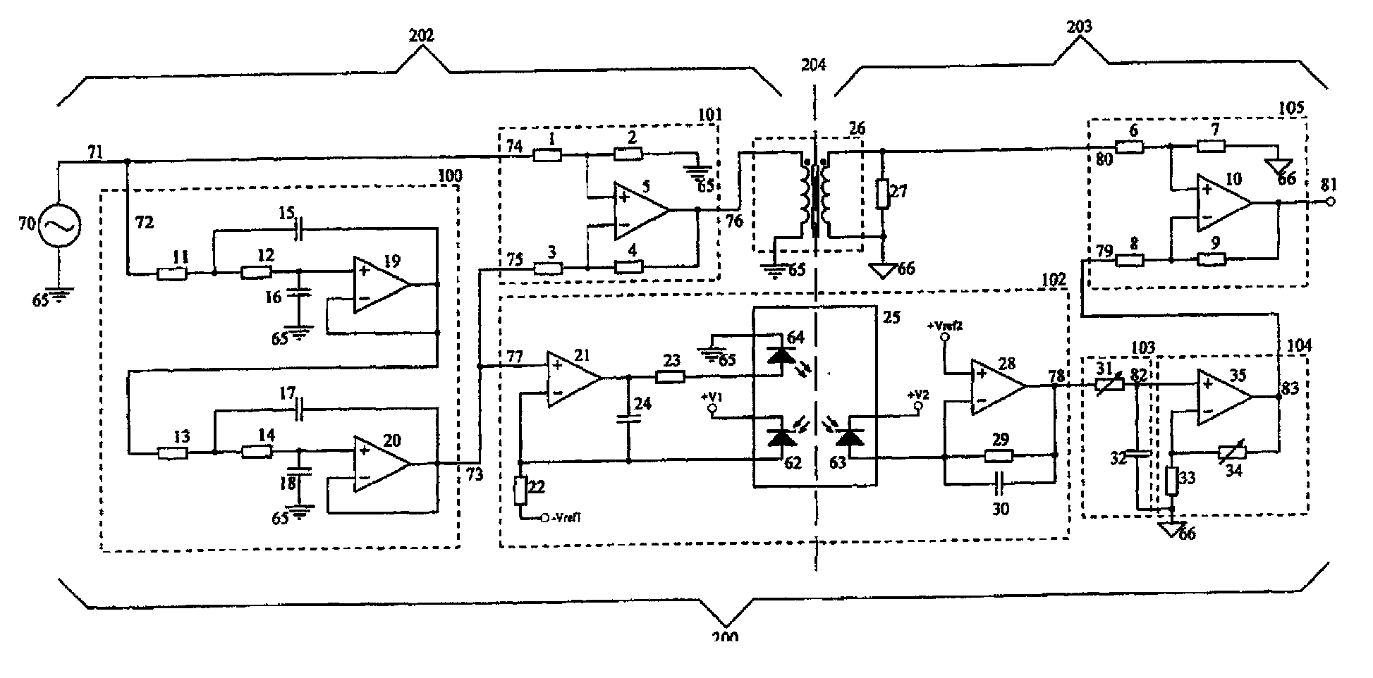
[0126] Figure 9 It is a schematic diagram of the structure of this embodiment. This embodiment is applicable to the application of single-ended signal input and differential signal output.

[0127] The difference between this embodiment and Embodiment 1 is that the high-frequency subtraction circuit uses a fully differential operational amplifier with differential output to drive the primary coil of the high-frequency transformer. The fully differential operational amplifier can choose ADA4927 of ADI Company or LMH6552 and LMH6554 of TI Company.

[0128] Correspondingly, the adding circuit also uses a fully differential amplifier, and the same amplifier as the high-frequency subtractor can be selected to form a proportional adding circuit. The two output terminals of the secondary coil of the high-frequency transformer are connected to the two input terminals of the full differential amplifier of the adding circuit, and the eight resistors of the adding circuit are selected...


PUM

PropertyMeasurementUnit
Bandwidthaaaaaaaaaa
Diameteraaaaaaaaaa
The inside diameter ofaaaaaaaaaa

Abstract

The invention provides a multipath linear isolation circuit which can be applied to measuring equipment, e.g., an oscilloscope. After linear isolation, the input signals are outputted, and input / output signals are electrically isolated. The multipath linear isolation circuit comprises a low frequency amplification circuit, a linear optical coupler circuit, a frequency compensating circuit, an intermediate frequency low pass circuit, an intermediate frequency subtraction circuit, an intermediate frequency transformer, a high frequency subtraction circuit, a high frequency transformer and an addition circuit. The input signals are divided into three parts of low frequency, intermediate frequency and high frequency and are isolated through different pathways. A low frequency signal pathway utilizes the linear optical coupler circuit for linear isolation, a frequency response compensating circuit is further added for compensating amplitude-frequency response recess caused by time delay of a linear optical coupler. For incompatible restriction of the low frequency and high frequency of transformers, frequency band width of the transformers is not very great. According to the multipath linear isolation circuit, the intermediate frequency transformer and the high frequency transformer are respectively utilized to isolate the intermediate frequency signals and the high frequency signals, so band width of the isolation circuit is greatly improved. The multipath linear isolation circuit can be conveniently applied to the measuring equipment, e.g., the oscilloscope.

Description

technical field [0001] The invention relates to electronic measuring equipment, in particular to a multi-line linear isolation circuit and an oscilloscope. Background technique [0002] The isolation circuit can transmit the electrical signal on the input side to the output side, but the input side and the output side are electrically isolated, or insulated, and there is only a small capacitance between the input side and the output side. The isolation circuit can improve the common mode rejection ratio during measurement, reduce interference, improve signal quality, and can also isolate dangerous voltages to protect equipment and personal safety. When multi-channel oscilloscopes measure at the same time, channel isolation can also measure multiple signals with different common-mode voltages to prevent short-circuit accidents caused by common ground between channels. [0003] From the frequency response of the processed signal and the isolation circuit, the isolation circui...

Claims


Application Information

Patent Timeline
IPC IPC(8): G01R15/22G01R13/00
Inventor 史慧王悦王铁军李维森
Owner RIGOL
Why Eureka
Try Eureka