
Single mechanical seal with elastic sealing ring and double mechanical seal with elastic sealing ring

An elastic seal and mechanical seal technology, which is applied to mechanical equipment, engine seals, engine components, etc., can solve the problems of difficulty in manufacturing mechanical seal parts, limited floating range of floating friction rings, and inability to maintain fit seals, etc., to achieve Save material, good floating effect, good sealing effect

Inactive Publication Date: 2014-06-25
浙江长城搅拌设备股份有限公司
View PDF5 Cites 3 Cited by
  • Summary
  • Abstract
  • Description
  • Claims
  • Application Information

AI Technical Summary

Problems solved by technology

[0004] In the above-mentioned prior art, the floating friction ring, the support seat, the spring seat and the shaft sleeve, etc. included in the floating ring assembly are all cylindrically fitted, and the O-shaped elastic sealing ring is added to the surface accuracy of the two sides in contact with it and its own deformation. The requirements are very strict. These factors lead to the limitation of the floating range of the floating friction ring. When the rotating shaft has a small jump or swing, the friction end faces of the friction pair cannot maintain a good fit and seal, causing leakage. Sealing components are difficult to manufacture and costly

Method used


Image

  • Single mechanical seal with elastic sealing ring and double mechanical seal with elastic sealing ring
  • Single mechanical seal with elastic sealing ring and double mechanical seal with elastic sealing ring
  • Single mechanical seal with elastic sealing ring and double mechanical seal with elastic sealing ring

Examples


Embodiment Construction

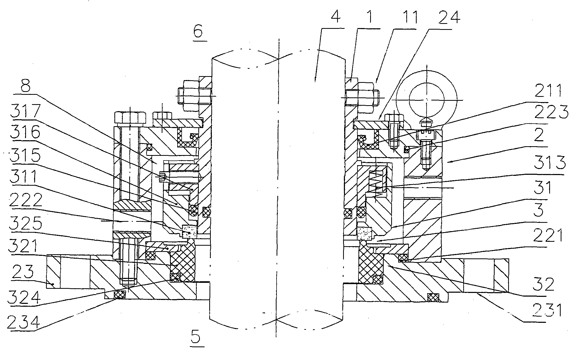
[0014] In order to better understand the improvement made by the present invention to the prior art, before describing in detail the single-end mechanical seal and the double-end mechanical seal with elastic sealing rings of the present invention, the combination of the prior art mentioned in the background technology section The accompanying drawings illustrate.

[0015] figure 1 The shown existing mechanical seal structure includes a shaft sleeve 1 fitted on a rotating shaft 4 , a sealing box 2 located on the periphery of the shaft sleeve 1 , and a pair of friction pairs 3 placed between the sealing box 2 and the shaft sleeve 1 . The friction pair 3 includes a floating ring assembly 31 and a fixed ring assembly 32 . The floating friction ring 311 in the floating ring assembly 31 realizes sealing and floating support by means of its supporting seat 316, the O-shaped elastic sealing ring 315 between the supporting seat 316 and the sleeve 1, and the spring 313 supporting the s...


PUM


Abstract

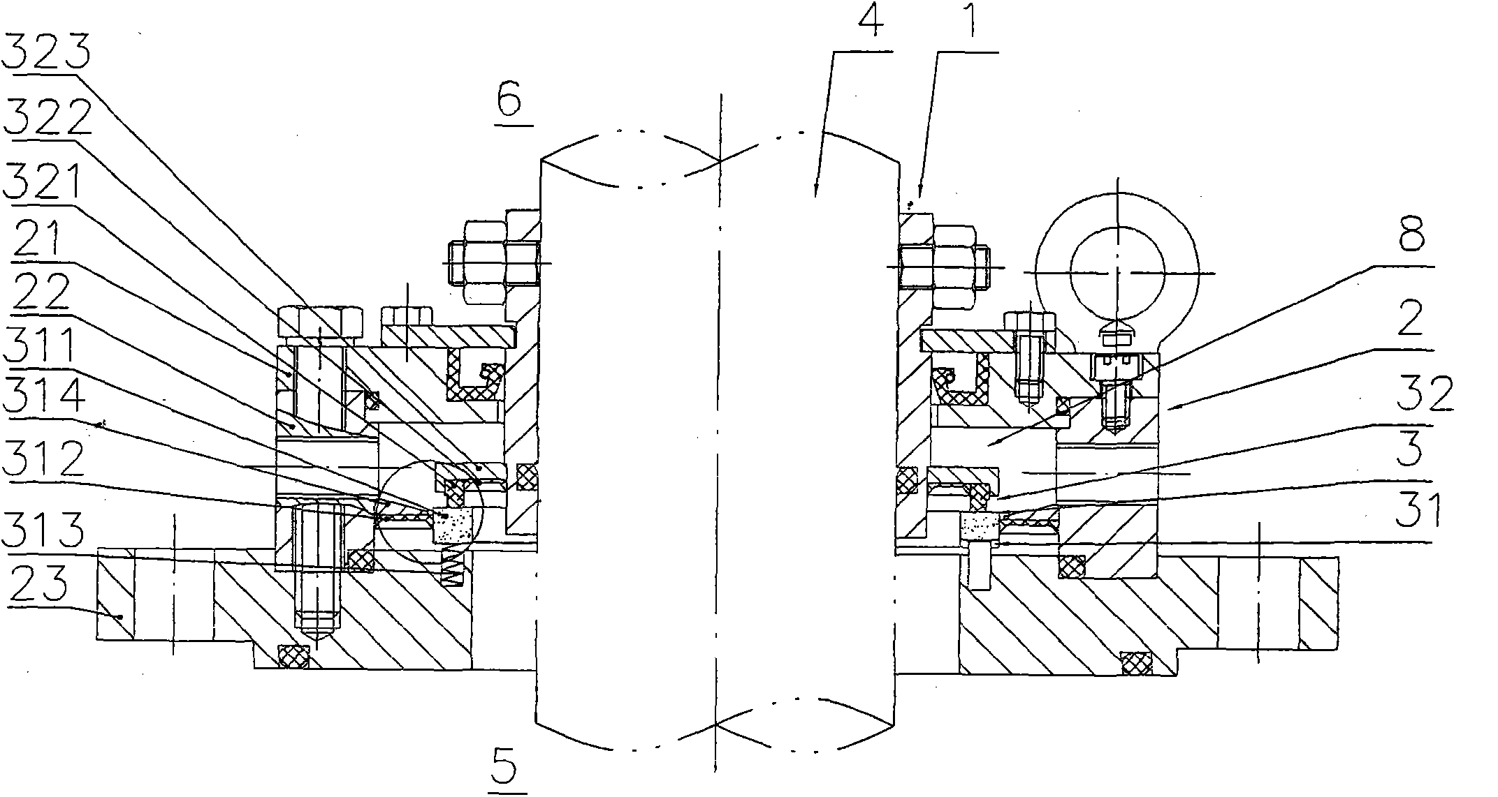
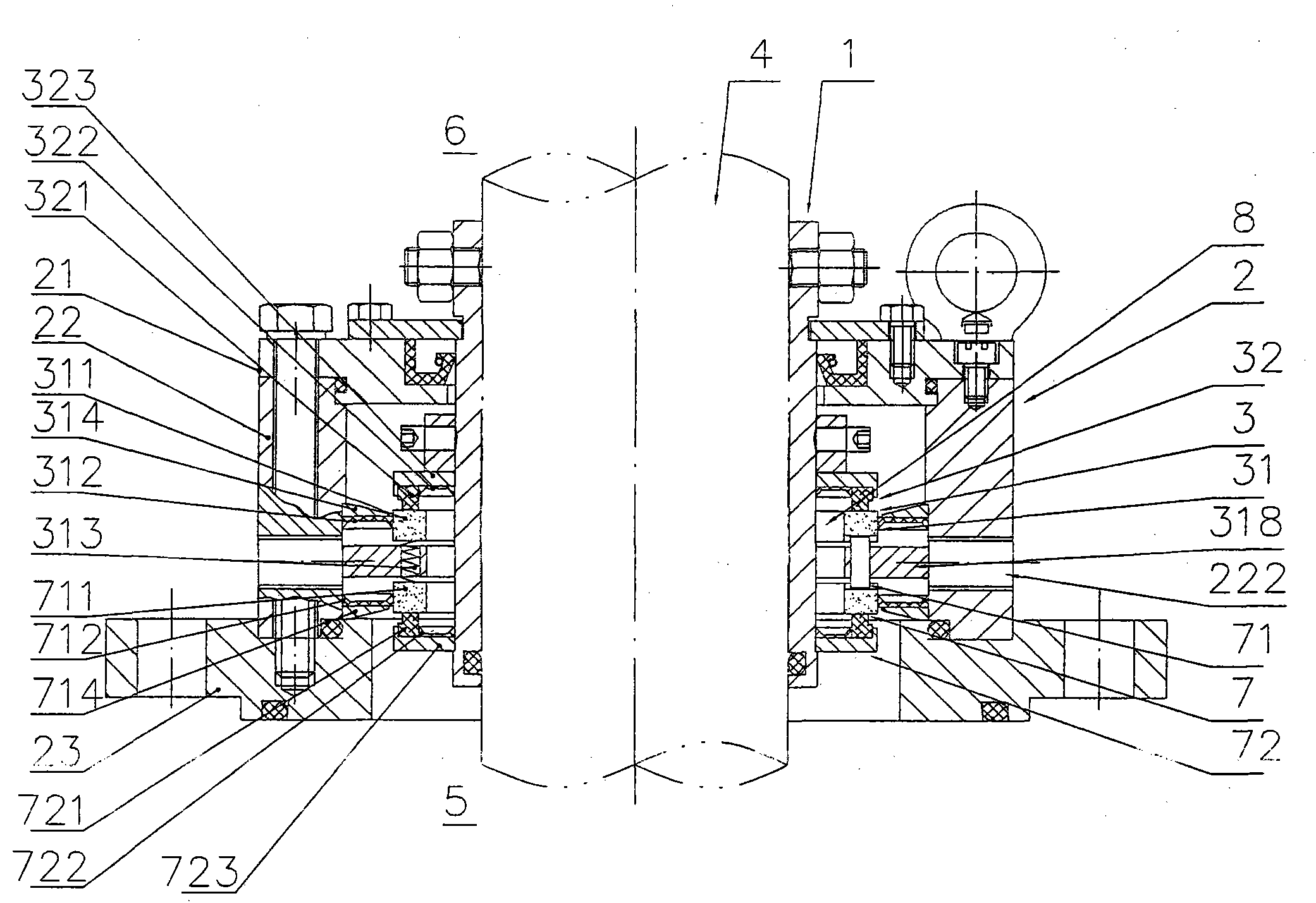
A single mechanical seal with an elastic sealing ring and a double mechanical seal with an elastic sealing ring are used for preventing fluid with certain pressure in a working container from leaking out of the working container along a rotary shaft penetrating through the working container. The single mechanical seal with the elastic sealing ring and the double mechanical seal with the elastic sealing ring respectively comprise a shaft sleeve installed on the rotary shaft in a sleeved mode, a sealing box located outside the shaft sleeve and a friction pair arranged between the sealing box and the shaft sleeve, wherein the friction pair comprises a floating ring assembly and a fixed ring assembly, and a floating friction ring in the floating ring assembly achieves the sealing and floating supporting by means of the elastic sealing ring arranged outside the floating friction ring, a sealing ring leaning piece on the lower pressure side of the floating friction ring and a spring abutting against the non-friction end of the floating friction ring. The floating effect of the floating friction rings is good, good sealing performance can also be kept even when the rotary shafts jump or swing by a large amplitude, the manufacturing difficulty of the parts is small, cost is reduced, and meanwhile the size of the mechanical seals is reduced so that design and installation are facilitated and materials are saved.

Description

technical field [0001] The invention relates to a single-end mechanical seal with an elastic sealing ring, which is used to prevent the fluid with a certain pressure inside the working container from leaking outside the working container along the rotating shaft penetrating through the working container. It includes a shaft sleeve set on the rotating shaft 1. A sealing box located on the periphery of the shaft sleeve and a pair of friction pairs placed between the sealing box and the shaft sleeve. [0002] The present invention also relates to a double-end mechanical seal with an elastic sealing ring. Compared with the above-mentioned single-end mechanical seal with an elastic sealing ring, the main difference is that the above-mentioned pair of friction pairs placed between the sealing box and the shaft sleeve are improved. There are two pairs of friction pairs. Background technique [0003] The mechanical seal, also known as the end face seal, has been used for more than ...

Claims


Application Information

Patent Timeline
Patent Type & Authority Applications(China)
IPC IPC(8): F16J15/16
Inventor 王洪群黄志坚周国忠虞培清吴亮章志耿
Owner 浙江长城搅拌设备股份有限公司
Learn More