Swing rod and sliding block reciprocating type solar wing auxiliary turnover mechanism

A reversing mechanism and reciprocating technology, which is applied in space navigation equipment, simulation devices of space navigation conditions, transportation and packaging, etc., can solve the problem that the solar wing cannot be freely unfolded and folded, and achieve good scalability and simple structure Effect

Active Publication Date: 2014-06-25
HARBIN INST OF TECH
View PDF5 Cites 7 Cited by
  • Summary
  • Abstract
  • Description
  • Claims
  • Application Information

AI Technical Summary

Problems solved by technology

[0003] The purpose of the present invention is to solve the problem that the current solar wing cannot be freely unfolded and folded during the ground test process, and to provide a swing bar slider reciprocating solar wing auxiliary turning mechanism

Method used


Image

  • Swing rod and sliding block reciprocating type solar wing auxiliary turnover mechanism
  • Swing rod and sliding block reciprocating type solar wing auxiliary turnover mechanism
  • Swing rod and sliding block reciprocating type solar wing auxiliary turnover mechanism

Examples


specific Embodiment approach 1

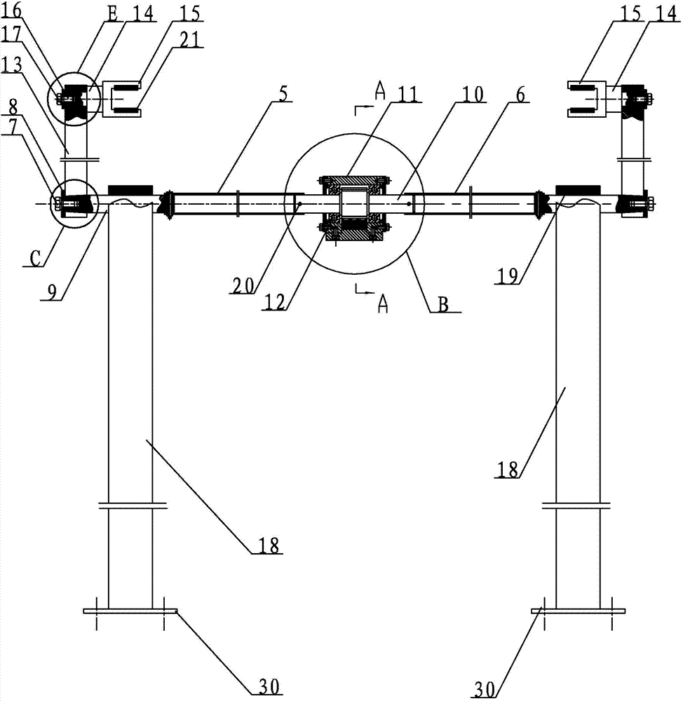
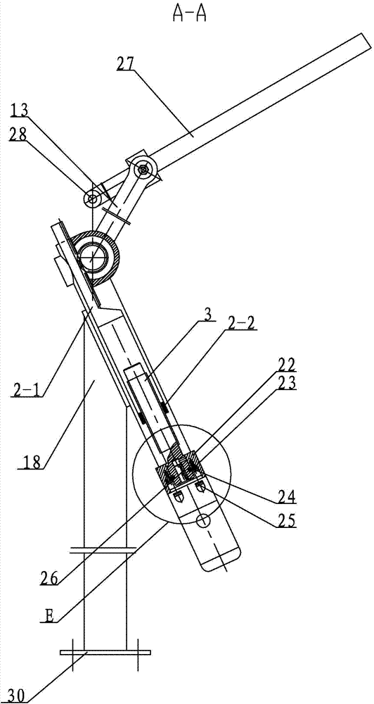
[0013] Specific implementation mode one: combine Figure 1-Figure 8 Describe this embodiment. In this embodiment, the pendulum slider reciprocating solar wing auxiliary turning mechanism includes a power device, a support mechanism, a transition shaft, a transmission device and two rocker mechanisms. The transition shaft is rotatably arranged on the support mechanism. The transmission device is set in the middle of the transition shaft, the power device is connected with the transmission device, and the two ends of the transition shaft are respectively rotatable and equipped with a rocker mechanism.

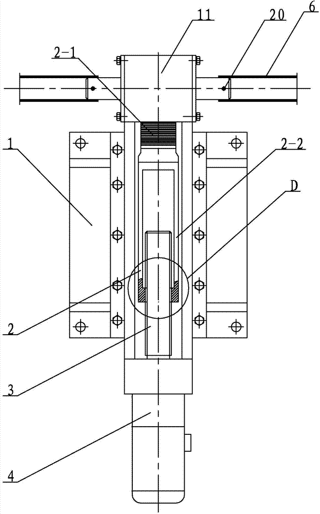
[0014] The power device includes a base 1, a rack 2, a lead screw 3 and a motor servo system 4, the rack 2 is slidably laid on the base 1, the motor servo system 4 is fixedly arranged on the base 1, and the lead screw 3 is arranged on the base 1 and connected to the output end of the motor servo system 4, the lead screw 3 is meshed with the rack 2;

[0015] The transition shaft ...

specific Embodiment approach 2

[0018] Specific implementation mode two: combination figure 1 Describe this embodiment, the supporting mechanism of this embodiment comprises two supports 18, two base plates 30 and a plurality of sliding bearings 19, the lower ends of two supports 18 are respectively fixedly arranged on the ground through a base plate 30, the two supports 18 The upper ends are respectively provided with a plurality of sliding bearings 19 . With such arrangement, the structure is simple, the stability is high, and it is convenient to support the power device, the transition shaft, the transmission device and the two rocker arm mechanisms. Other compositions and connections are the same as in the first embodiment.

specific Embodiment approach 3

[0019] Specific implementation mode three: combination figure 1 with Figure 5 Referring to this embodiment, the transmission device of this embodiment further includes two pins 20 , and the two ends of the gear shaft 10 are respectively connected to the left coupling 5 and the right coupling 6 through one pin 20 . With such a setting, the connection method is simple, and it is convenient for installation and maintenance. Other compositions and connections are the same as those in the second embodiment.


PUM


Abstract

The invention relates to a solar wing auxiliary turnover mechanism, in particular to a swing rod and sliding block reciprocating type solar wing auxiliary turnover mechanism. The problem that a solar wing cannot be freely unfolded and folded in a current ground test is solved. The swing rod and sliding block reciprocating type solar wing auxiliary turnover mechanism comprises a power device, a supporting mechanism, a transitional shaft, a transmission device and two rocker arm mechanisms, the transitional shaft is rotatably arranged on the supporting mechanism, the transmission device is arranged in the middle of the transitional shaft, the power device is connected with the transmission device, and the two ends of the transitional shaft are respectively and rotatably provided with one rocker arm mechanism. A set of the power device and the transmission device is adopted, power is transmitted in two directions, and the two rocker arm mechanisms are driven to control the solar wing to be folded and unfolded. The problem that a solar wing driving mechanism cannot be folded and unfolded on the ground is effectively solved, and high reliability and good expansibility are achieved. The swing rod and sliding block reciprocating type solar wing auxiliary turnover mechanism is used for assisting the solar wing in turning over.

Description

technical field [0001] The invention relates to an auxiliary turning mechanism for a solar wing, in particular to a reciprocating auxiliary turning mechanism for a swing bar slider. Background technique [0002] In the heat balance test of the first prototype of the lander, the conditions of earth-moon transfer, circumlunar operation, landing operation, and day-to-night conversion are arranged. It is necessary to adjust the deployment angle of the solar wing under different operating conditions in the space environment simulator. In the thermal balance test of the lander, the +Y and -Y solar wings need to simulate the actual on-orbit situation, and they must be deployed and retracted in the space environment simulator many times. Since the solar wing drive mechanism does not have the ability to deploy and retract on the ground, it is necessary to Develop a set of solar wing deployment mechanism for ground test. Contents of the invention [0003] The purpose of the present...

Claims


Application Information

Patent Timeline
IPC IPC(8): B64G7/00
Inventor 李楠高海波杨怀广丁亮邓宗全
Owner HARBIN INST OF TECH
Why Eureka
Try Eureka