
Raw material crushing system with back blowing function

A raw material crushing and functional technology, applied in grain processing and other directions, can solve the problems of material deposition, uneven particles, and easy deposition of materials, and achieve the effect of avoiding raw material deposition and uniform particles

Inactive Publication Date: 2016-01-20
CHENGDU QIAOFENG TECH DEV
View PDF6 Cites 0 Cited by
  • Summary
  • Abstract
  • Description
  • Claims
  • Application Information

AI Technical Summary

Problems solved by technology

[0004] The purpose of the present invention is to overcome the phenomenon that some materials are prone to deposit during the crushing of the above-mentioned existing crushing equipment, resulting in the problem that the crushed particles are uneven, and a raw material crushing system with a back blowing function is designed. The pipeline is connected to the air pump so that the raw materials are blown up during crushing, avoiding the deposition of raw materials, and making the crushed particles uniform, which solves the problem that some materials are prone to deposit during crushing in existing crushing equipment, resulting in uneven crushed particles question

Method used


Image

  • Raw material crushing system with back blowing function
  • Raw material crushing system with back blowing function

Examples


Embodiment 1

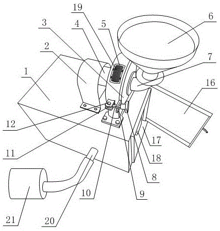
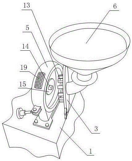
[0017] Such as figure 1 , figure 2 As shown, a raw material crushing system with a back blowing function is provided, including a hollow support box 1, a crushing chamber and a motor 4 are arranged on the top surface of the support box 1, and the crushing chamber and the motor 4 are fixed on the support box 1, a hopper 6 is installed on the crushing chamber, and the hopper 6 communicates with the interior of the crushing chamber. A cylindrical cavity is provided inside the crushing chamber, and the motor 4 is connected to a rotating shaft 14, and the rotating shaft 14 is far away from the motor. One end of 4 extends into the cavity, and the rotating shaft 14 is sleeved with a chopping runner 15, and the chopping runner 15 is arranged inside the cavity, and a pipeline 20 is arranged on the side wall of the support box 1, and one end of the pipeline 20 An air pump 21 is connected, and the air pump 21 is arranged on the outside of the support box 1. The other end of the pipelin...

Embodiment 2

[0019] Such as figure 1 , figure 2As shown, on the basis of Embodiment 1, the crushing chamber includes a housing 5 with an opening at one end, an end cover 3 is arranged on the housing 5, and the end cover 3 seals the opening end of the housing 5, and the end cover 3 and the motor 4 are respectively arranged on the symmetrical sides of the casing 5, the cavity is arranged in the casing 5, the dust screen 19 is arranged on the casing 5, the casing 5 is installed on the supporting box 1, and the casing 5 is set There are two fixed buckles, one end of the fixed buckle is fixed with the housing 5, a rotating pin is arranged between the fixed buckles, the two ends of the rotating pin pass through the two fixing buckles respectively, the end cover 3 is connected with the rotating pin, and the end cover 3 It can rotate around the rotating pin; the housing 5 is provided with two mutually parallel mounting blocks 11, one end of the mounting blocks 11 is fixed to the outer wall of th...


PUM


Abstract

The invention discloses a raw material grinding system with a blowback function. The raw material grinding system is characterized in that both a grinding chamber and a motor are fixedly arranged on a supporting box; a hopper is mounted on the grinding chamber and is communicated with the grinding chamber; the grinding chamber is provided with a cavity in a cylindrical structure; the motor is connected with a rotary shaft; one end of the rotary shaft extends into the cavity; the rotary shaft is sleeved with a cutting rotary wheel; the cutting rotary wheel is arranged in the cavity; a pipeline is arranged on the supporting box; one end of the pipeline is connected with an air pump; the air pump is arranged outside the supporting box; the pipeline extends into the supporting box, is communicated with the grinding chamber and is higher than the bottom end surface of the cavity; an air outlet is formed in the top end of the grinding chamber and is communicated with the cavity; a dust baffle sieve is arranged in the air outlet, is fixed on the grinding chamber and completely covers the air outlet. According to the system, the pipeline is connected with the air pump, so that raw materials are blown up during grinding, the raw material deposition is avoided, and ground particles are uniform.

Description

technical field [0001] The invention relates to a system, in particular to a raw material crushing system provided with a blowback function, and belongs to the field of biomechanics. Background technique [0002] Crushing is the application of external force to solid materials to split them into smaller particles, a unit operation belonging to powder engineering. The solid raw materials and coal used in chemical production often need to be crushed to a certain particle size before they can be used. For example, in most chemical reactions involving solid particles, reducing the particle size can increase the interphase contact surface and increase the reaction rate. In the leaching operation, reducing the particle size can not only increase the interphase contact surface, but also shorten the diffusion distance of the substance in the particle and increase the leaching rate. In the production process of ceramics, cement, pigments, catalysts, etc., in order to obtain a unifo...

Claims


Application Information

Patent Timeline
Patent Type & Authority Patents(China)
IPC IPC(8): B02C18/14B02C18/16B02C23/18
Inventor 王勇
Owner CHENGDU QIAOFENG TECH DEV
Learn More