Low temperature gas supply device, heat transfer medium-cooling device, and low temperature reaction control device
A low-temperature gas and supply device technology, applied in gas and gas/vapor mixing, household refrigeration devices, applications, etc., can solve the problems of flow pulsation, temperature instability, low temperature gas temperature instability, etc., to achieve stable temperature control and expansion Select range, avoid specific effects
- Summary
- Abstract
- Description
- Claims
- Application Information
AI Technical Summary
Problems solved by technology
Method used
Image

Examples
no. 1 approach )
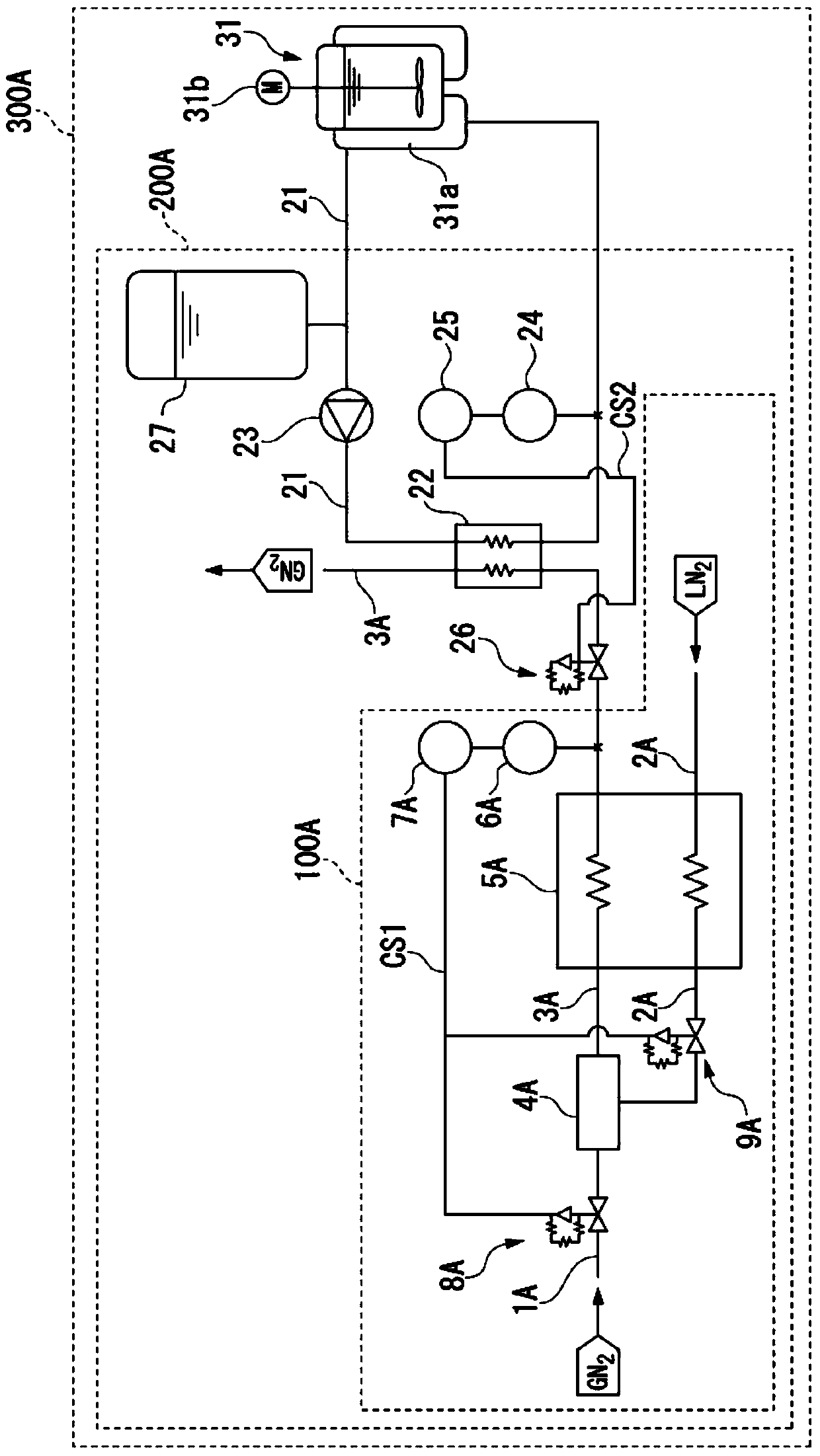
[0058] First, the configurations of the low-temperature gas supply device 100A, the heating medium cooling device 200A, and the low-temperature reaction control device 300A according to the first embodiment to which the present invention is applied will be described. figure 1 It is a system diagram of the first embodiment of the low-temperature gas supply device, the heating medium cooling device, and the low-temperature reaction control device of the present invention.
[0059] Such as figure 1 As shown, the low-temperature gas supply device 100A according to the first embodiment of the present invention includes a normal-temperature path 1A through which a normal-temperature nitrogen gas (GN) which is a high-temperature gas compared with a low-temperature liquefied gas described later is introduced from one end. 2 ) NNG; low temperature path 2A, from one end into liquefied nitrogen (LN 2 ) LN (for example, -196°C); mixing path 3A, for the mixed gas and low-temperature nitro...
no. 2 approach )
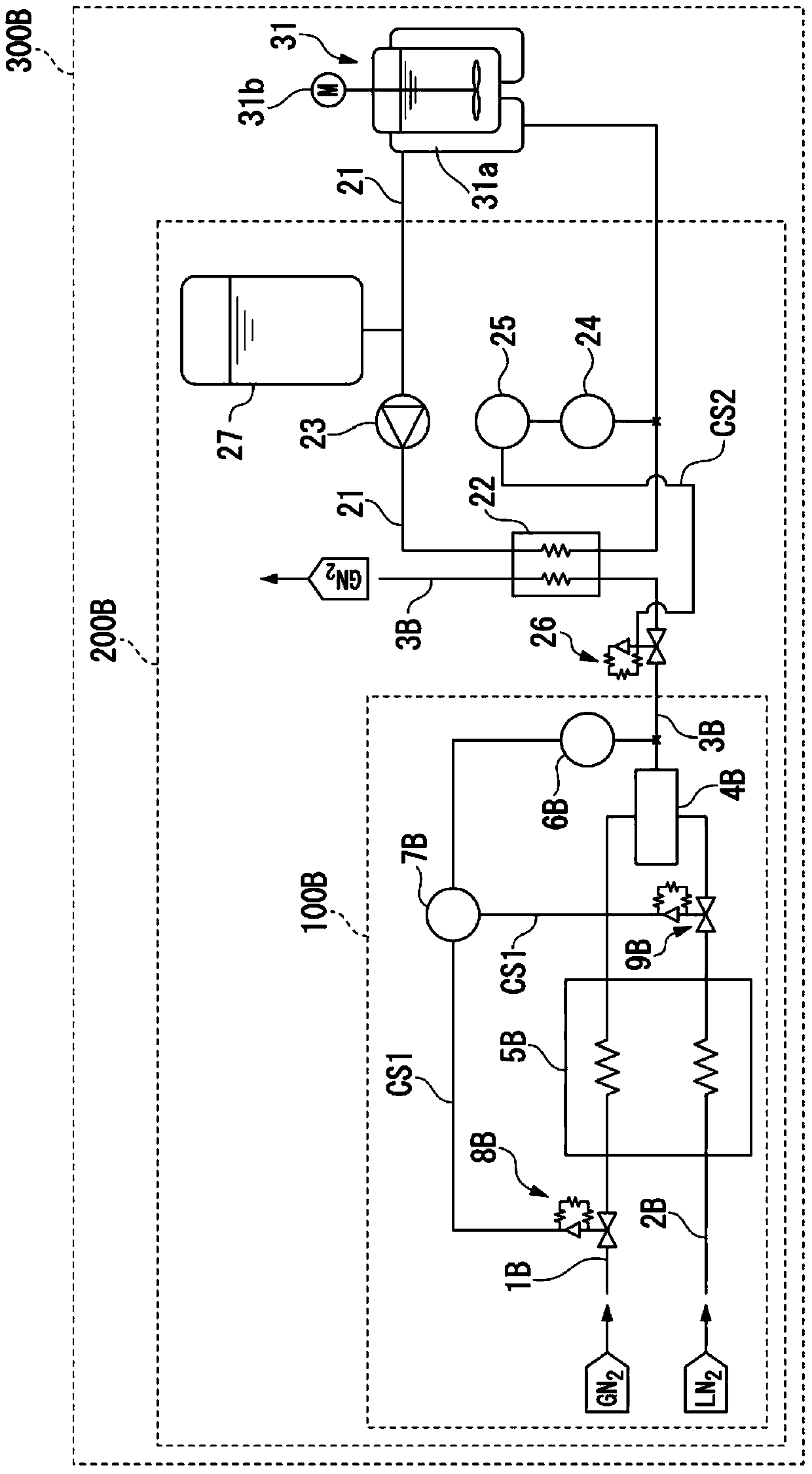
[0074] Next, a second embodiment of the present invention will be described. figure 2 It is a system diagram of the second embodiment of the low-temperature gas supply device, the heating medium cooling device, and the low-temperature reaction control device of the present invention.
[0075] Such as figure 2 As shown, the cryogenic gas supply device 100B according to the second embodiment of the present invention is provided with a normal temperature path 1B, and a normal temperature nitrogen gas (GN 2 ) NNG; low temperature path 2B, from one end into liquefied nitrogen (LN 2 ) LN (for example, -196°C); the mixing path 3B, for the flow of low-temperature nitrogen refrigerant described later; the first heat exchanger 5B, through which the normal-temperature nitrogen gas NNG introduced from the normal-temperature path 1B and the liquefied nitrogen gas introduced from the low-temperature path 2B Nitrogen and LN perform heat exchange with each other, and are discharged as gas...
no. 3 approach )
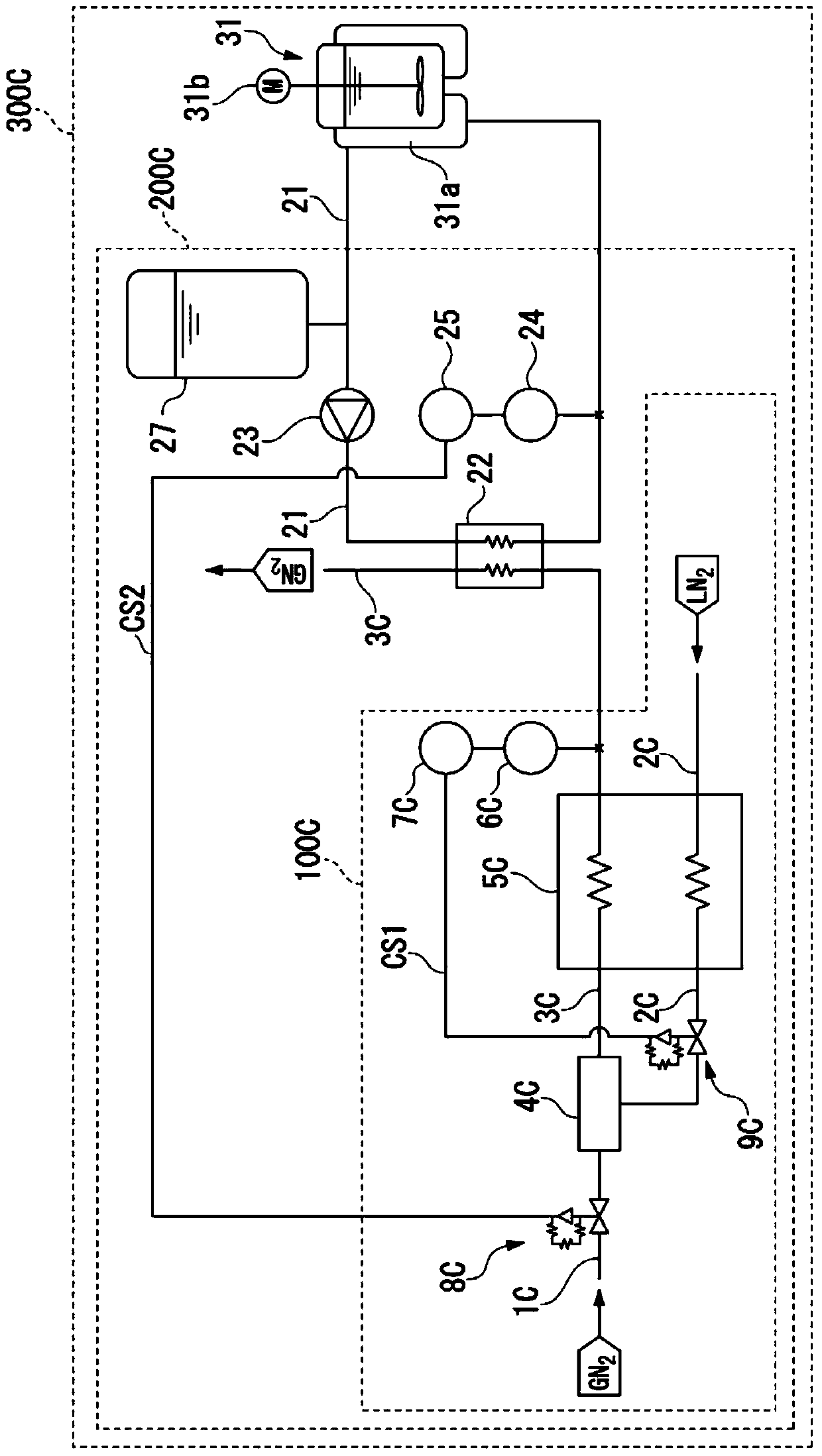
[0090] Next, a third embodiment of the present invention will be described. image 3 It is a system diagram of the third embodiment of the low-temperature gas supply device, the heating medium cooling device, and the low-temperature reaction control device of the present invention.
[0091] Such as image 3 As shown, the low-temperature gas supply device 100C according to the third embodiment of the present invention includes: a normal-temperature path 1C through which a normal-temperature nitrogen gas (GN 2 ) NNG; low temperature path 2C, from one end into liquefied nitrogen (LN 2 ) LN (for example, -196°C); mixing path 3C, for the flow of the mixed gas and low-temperature nitrogen refrigerant described later; ejector (mixing mechanism) 4C, mixing the normal temperature nitrogen NNG introduced from the other end of the normal temperature path 1C and from The gas resulting from the gasification of liquefied nitrogen LN (hereinafter referred to as "liquefied nitrogen gasifica...
PUM
 Abstract
Description
Claims
Application Information
 - R&D
- Intellectual Property
- Life Sciences
- Materials
- Tech Scout
- Unparalleled Data Quality
- Higher Quality Content
- 60% Fewer Hallucinations
Browse by: Latest US Patents, China's latest patents, Technical Efficacy Thesaurus, Application Domain, Technology Topic, Popular Technical Reports.
© 2025 PatSnap. All rights reserved.Legal|Privacy policy|Modern Slavery Act Transparency Statement|Sitemap|About US| Contact US: help@patsnap.com