Multi-phase phase-locked loop circuit for clock data recovery
A clock data recovery, multi-phase technology, applied in the direction of electrical components, automatic power control, etc., to achieve the effect of increasing the transmission rate range
- Summary
- Abstract
- Description
- Claims
- Application Information
AI Technical Summary
Problems solved by technology
Method used
Image

Examples
Embodiment Construction
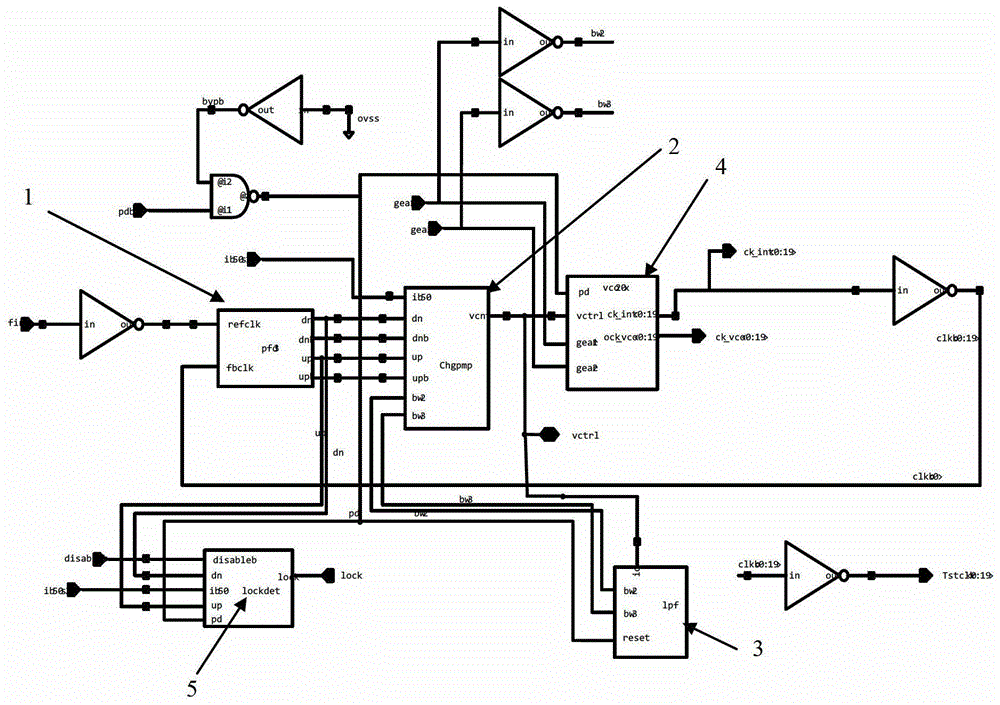
[0036] Such as figure 1 Shown is the multiphase PLL circuit diagram of the embodiment of the present invention; the multiphase PLL circuit used for clock data recovery in the embodiment of the present invention includes a frequency and phase detector 1, a charge pump 2, and a loop filter connected in sequence 3. Voltage-controlled oscillator 4 and lock-up monitor circuit 5 . The signal pd is used to provide a shutdown signal for the loop filter 3, the voltage-controlled oscillator 4 and the lock-up monitor circuit 5, the signal pdb is the inverse signal of the signal pd, and the signals ib50, ib50s1 and ib50s2 are used to provide positive power supplies Voltage, signal ovss is used to provide negative voltage. The signal gear1 is the first gear signal gear1, the signal gear2 is the second gear signal gear2; the signal bw2 is the inversion signal of the signal gear1, and the signal bw,3 is the inversion signal of the signal gear2.
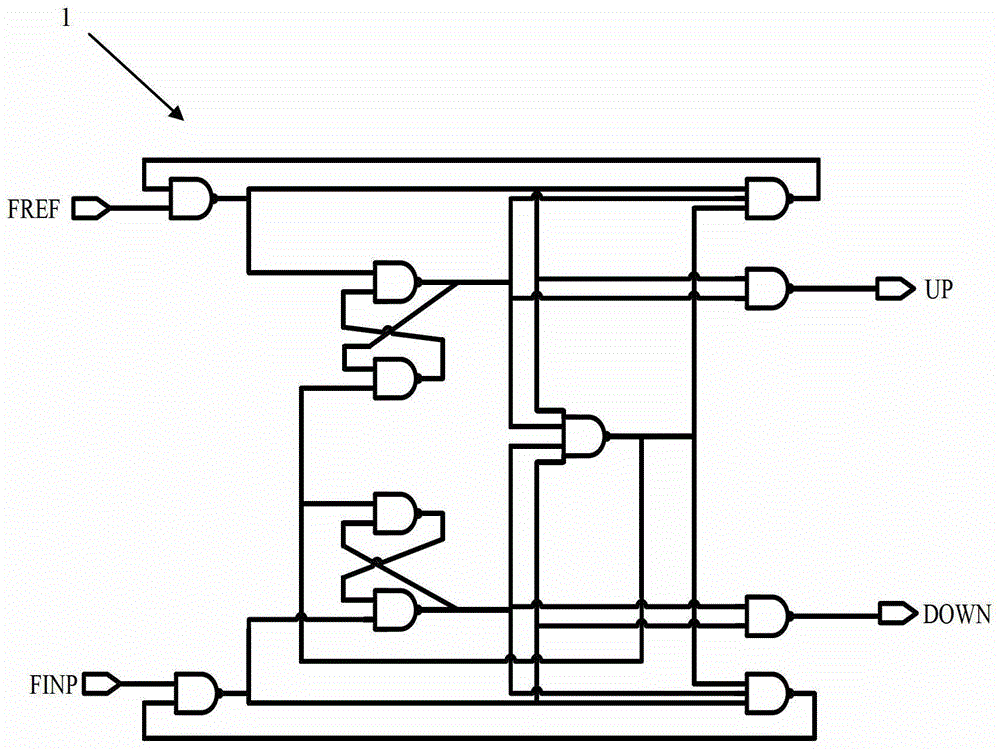
[0037] The input terminal of the frequency ...
PUM
 Abstract
Description
Claims
Application Information
 - R&D
- Intellectual Property
- Life Sciences
- Materials
- Tech Scout
- Unparalleled Data Quality
- Higher Quality Content
- 60% Fewer Hallucinations
Browse by: Latest US Patents, China's latest patents, Technical Efficacy Thesaurus, Application Domain, Technology Topic, Popular Technical Reports.
© 2025 PatSnap. All rights reserved.Legal|Privacy policy|Modern Slavery Act Transparency Statement|Sitemap|About US| Contact US: help@patsnap.com