
Space positioning system and method

A space positioning and space position technology, applied in positioning, radio wave measurement system, measuring device, etc., can solve the problems of low precision and high implementation cost, achieve the effects of improving applicability, real-time tracking, and overcoming high implementation complexity

Inactive Publication Date: 2016-07-20
CHENGDU IDEALSEE TECH
View PDF7 Cites 22 Cited by
  • Summary
  • Abstract
  • Description
  • Claims
  • Application Information

AI Technical Summary

Problems solved by technology

[0004] The purpose of the present invention is to provide a space positioning system and method to solve the problems of high implementation cost and low precision in the existing space positioning technical solutions, and to overcome the limitations of the existing positioning technology on site requirements and distance restrictions

Method used


Image

  • Space positioning system and method
  • Space positioning system and method
  • Space positioning system and method

Examples


Embodiment 1

[0045] spatial positioning system

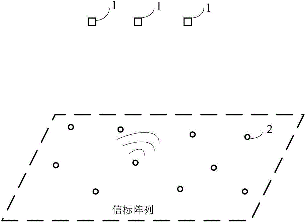
[0046] The spatial positioning system of the embodiment of the present invention includes at least three beacons and at least one positioning terminal, see figure 1 , is a schematic structural diagram of a spatial positioning system according to an embodiment of the present invention,figure 1 Among them, the label 2 represents a beacon, and 1 represents a positioning terminal. Multiple beacons are distributed and arranged in the space to be positioned to form a beacon array. The beacons are used to generate low-frequency electromagnetic fields; each positioning terminal receives the signals generated by multiple beacons. low-frequency electromagnetic field, and calculate the spatial position of the positioning terminal according to the received low-frequency electromagnetic field data generated by at least three beacons. In the embodiment of the present invention, the positioning terminal may be a mobile device, such as a smart phone, a sm...

Embodiment 2

[0074] Spatial Orientation Method

[0075] see Figure 14 , is a schematic flow chart of the spatial positioning method of the present invention, including the following steps:

[0076] S101: In the space to be positioned, a plurality of beacons are preset to generate a low-frequency electromagnetic field;

[0077] S102: The positioning terminal receives the low-frequency electromagnetic fields generated by the plurality of beacons;

[0078] S103: Determine the spatial position where the positioning terminal is located according to the received low-frequency electromagnetic field data generated by multiple beacons.

[0079] In the embodiment of the present invention, wireless or wired communication is used between multiple beacons to form an ad hoc network; after the ad hoc network is formed, all beacons are coordinated by the temporary host of the ad hoc network , sequentially measure the distance between itself and other beacons, establish a space coordinate system, and...


PUM


Abstract

The invention discloses a space positioning system comprising at least three beacons and at least one positioning terminal. The beacons are distributed in to-be-localized space and are used for generating low-frequency electromagnetic fields. Each positioning terminal receives low-frequency electromagnetic fields generated by the multiple beacons and calculates a spatial position of the positioning terminal according to the received low-frequency electromagnetic fields generated by the at least three beacons. Meanwhile, the invention also discloses a space positioning method. Therefore, defects of high implementation complexity, high deployment cost, large positioning error, and delayed positioning information updating of the existing positioning scheme can be overcome effectively. On the basis of the low-cost scheme, the indoor large-range precise real-time tracking can be realized; the environment requirement is loose and no metal and magnetic interference exists; and applicability of the space positioning scheme in different environment scenes can be improved obviously.

Description

technical field [0001] The invention relates to space positioning technology, in particular to a space positioning system and method. Background technique [0002] In recent years, with the development of wireless communication technology and the gradual popularization of smart terminals, the application of Location Based Service (LBS) has provided convenient experience for production and life in many fields, and has become an important part of social life. In an unobstructed open environment, using GPS satellite signals and communication base station signals to achieve positioning has become a common method in the industry. However, the stability of positioning using GPS satellite signals and communication base station signals is poor, and it is easily affected by factors such as signal occlusion and signal coverage. At the same time, the positioning error of GPS satellite signals and communication base station signals often reaches several meters or even tens of meters, wh...

Claims


Application Information

Patent Timeline
Patent Type & Authority Applications(China)
IPC IPC(8): G01S5/10
CPCG01S5/10
Inventor 李小虎张超
Owner CHENGDU IDEALSEE TECH
Learn More