Spiral winding tube type heat exchanger and variable flow spiral tube cooling device

A tubular heat exchanger, spiral winding technology, applied in the direction of heat exchanger type, heat exchanger shell, indirect heat exchanger, etc. The improvement of the thermal effect is not obvious, and the problems such as installation cannot be achieved, so as to reduce the possibility and scaling tendency, solve the large difference in convective heat transfer coefficient, and achieve the effect of stable operation

Active Publication Date: 2014-06-18
江苏雨灵机械科技有限公司
View PDF6 Cites 3 Cited by
  • Summary
  • Abstract
  • Description
  • Claims
  • Application Information

AI Technical Summary

Problems solved by technology

However, the helically wound tube heat exchanger cannot be installed on the helically wound tube bundle by using the existing heat exchanger baffle technology because the tubes are wound into a helical shape.
For this problem, relevant personnel in this industry have done a lot of work but still can't solve it, resulting in the inability to use baffles to enhance heat transfer in the shell side of the spiral wound tube heat exchanger
Therefore, the overall heat transfer effect of the spiral wound tube heat transfer surface is not significantly improved.

Method used


Image

  • Spiral winding tube type heat exchanger and variable flow spiral tube cooling device
  • Spiral winding tube type heat exchanger and variable flow spiral tube cooling device
  • Spiral winding tube type heat exchanger and variable flow spiral tube cooling device

Examples


Embodiment 1

[0026] Example 1 Spiral wound tube heat exchanger

[0027] Figure 1 shows the structure of a preferred embodiment of a spiral wound tube heat exchanger of the present invention, which is used for water cooling of fluids such as lubricating oil.

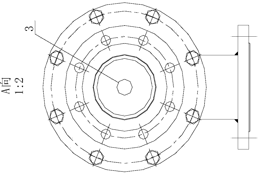
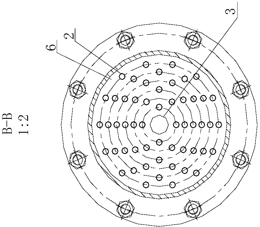
[0028] Such as Picture 1-1 As shown, the spirally wound tube heat exchanger includes a shell 1 and a spiral tube bundle with two ends of the shell installed on the tube sheet 6. The two ends of the shell 1 are provided with a tube pass inlet 1-1 and a tube pass outlet 1. -2. On the side wall of the shell 1, there are shell side inlets 1-3 and shell side outlets 1-4. The two ends of the spiral tube bundle composed of multiple spiral tubes 2 are installed on the tube plates 6 at both ends of the heat exchanger.

[0029] Structural combination of spiral tube bundle Picture 1-1 with Figure 1-4 As shown, the spiral tube bundle is composed of 6 layers of spiral tubes 2 concentrically wound into a spiral shape, and each layer of spiral tubes 2 use...

Embodiment 2

[0047] Example 2 Variable flow spiral tube reverse winding type cooling device

[0048] Such as figure 2 Shown is a variable-flow spiral tube reverse-wound cooling device, and the spiral tube heat exchanger adopts the structure of Embodiment 1.

[0049] The cooling device includes a spiral tube heat exchanger, a temperature sensor, a control system, a variable frequency motor, and a pump driven by the variable frequency motor. The temperature sensor is arranged on the tube side outlet pipeline of the spiral wound tube heat exchanger. The output end is connected with the input end of the control system, the input end of the variable frequency motor is connected with the output end of the control system, and the outlet of the pump is connected with the shell side inlet of the spiral wound tube heat exchanger.

[0050] The temperature at the outlet of the winding tube heat exchanger is measured by a temperature sensor. The temperature sensor measures the temperature and uploads it to ...


PUM


Abstract

The invention discloses a spiral winding tube type heat exchanger and a variable flow cooling device. The spiral winding tube type heat exchanger comprises a shell (1) and a spiral tube bundle located at the two ends in the shell and installed on a tube plate (6), a tube pass inlet (1-1), a tube pass outlet (1-2), a shell pass inlet (1-3) and a shell pass outlet (1-4) are formed in the shell (1), the spiral tube bundle is composed of a plurality of layers of spiral tubes (2) which are wound into the spiral shape concentrically, and a plurality of spiral tubes (2) are wound in the same direction to form each layer of spiral tubes (2); a plurality of baffle plates (4) are installed between the layers of spiral tubes (2), and the two ends of each baffle plate (4) are fixed to the corresponding spiral tube (2). Not only can the heat exchange strength of fluid in the tubes be guaranteed, but also convection heat exchange of fluid outside the tubes can be strengthened; the exterior of the winding tube type heat exchanger is connected with a temperature sensor, a control system, a variable frequency motor, a pump and other system parts, the flowing amount of cooling mediums can be adjusted in real time, the winding tube type heat exchanger adapts to changes of cooling loads, and the energy-saving requirement is met; meanwhile, the winding tube type heat exchanger has the advantages of preventing scaling and being resistant to corrosion.

Description

Technical field [0001] The invention belongs to the technical field of convective heat transfer, energy-saving and consumption-reducing fluid heat exchange, and specifically relates to a variable-flow spiral tube cooling device that can adjust the flow of heat exchange medium in real time and has a small difference in convective heat transfer coefficient between the inside and outside of the spiral tube, and a Spiral wound tube heat exchanger with baffles. Background technique [0002] Traditional shell-and-tube heat exchangers have limited heat exchange tubes and a small heat exchange area per unit volume; the safe operation of the equipment is often limited by the maximum working temperature of the heat exchange medium, and whether there will be flow rates such as dead angles. The drop zone causes thermal stress damage on the heat exchange surface due to local uneven heat exchange; when the equipment is running for a long time, the tube bundle is easy to scale and is not easy t...

Claims


Application Information

Patent Timeline
Patent Type & Authority Applications(China)
IPC IPC(8): F28D7/02F28F9/24F28F27/00
Inventor 王迎慧王茹黄继军朱林林
Owner 江苏雨灵机械科技有限公司
Why Eureka
Try Eureka