


Quick Research
Generate reliable direction feasibility study reports for your R&D in just a few steps.

Technical Q&A
Discover and master advanced knowledge NOW. Basics, ideas, possibilities, all at once.

Find Solutions
As an expert in R&D theories, this can generate solutions to your technical problems instantly.

Evaluate Feasibility
Analyze your overall solution with one click, know your potential R&D risks in advance.

Monitor Landscape
Get weekly tech updates, stay abreast of the latest tech innovations and key insights.
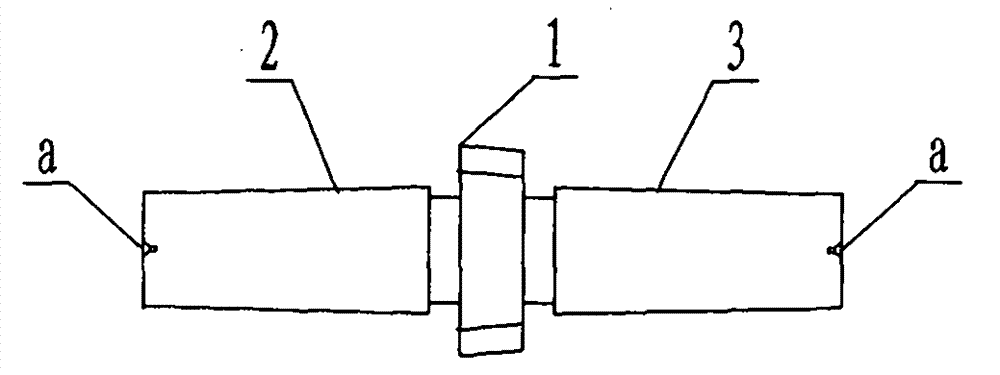
Taper-shank slotting cutter grinding device
A technology of gear shaping cutter and tapered shank, which is applied in the field of numerical control processing devices, can solve problems such as difficult correction, inconvenient production and use of tapered shank gear shaping cutter, and impossibility of grinding and testing of tapered shank gear shaping cutter, so as to achieve precision grinding Cutting accuracy and work efficiency are improved, and the effect of ensuring machining accuracy
- Summary
- Abstract
- Description
- Claims
- Application Information
AI Technical Summary
Problems solved by technology
Method used
Image

Examples
Embodiment Construction
[0026] In order to enable those skilled in the art to better understand the technical solutions of the present invention, the present invention will be further described in detail below in conjunction with the accompanying drawings and specific embodiments.
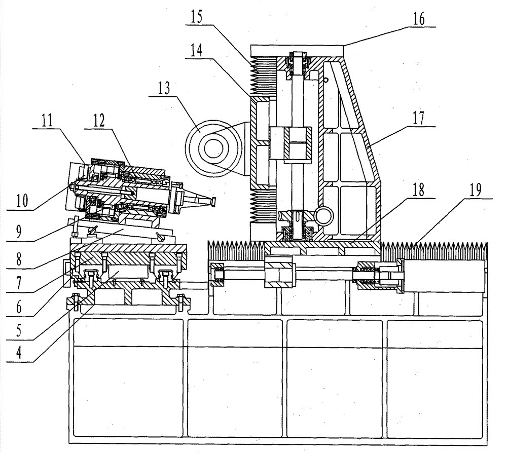
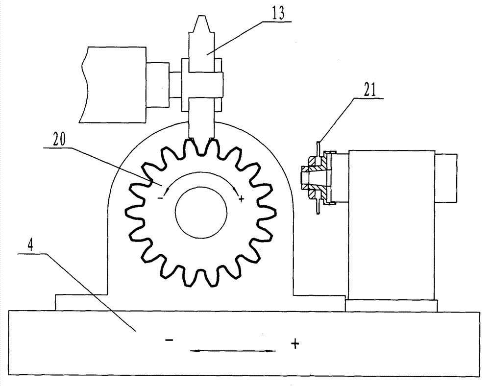
[0027] like figure 2 As shown, a grinding device for a tapered shank gear shaper cutter 20 includes a feed table controlled by a numerical control system. The feed table includes an X-axis feed table 4, a Y-axis feed table 16 and a Z-axis feed table. Give workbench 19, three feed workbenches all can move back and forth. The X-axis, the Y-axis and the Z-axis are perpendicular to each other, and both the X-axis and the Z-axis are located in the horizontal plane.
[0028] X-axis feed table 4
[0029] The X-axis feed table 4 is controlled by the numerical control system and can drive the tapered shank gear shaper cutter 20 to reciprocate in the horizontal direction "+" and "-", such as image 3 shown. The amplitude of mo...
PUM
 Abstract
Description
Claims
Application Information
 - R&D Engineer
- R&D Manager
- IP Professional
- Industry Leading Data Capabilities
- Powerful AI technology
- Patent DNA Extraction
Browse by: Latest US Patents, China's latest patents, Technical Efficacy Thesaurus, Application Domain, Technology Topic, Popular Technical Reports.
© 2024 PatSnap. All rights reserved.Legal|Privacy policy|Modern Slavery Act Transparency Statement|Sitemap|About US| Contact US: help@patsnap.com