
Low-to-high logic level conversion circuit

A logic level and conversion circuit technology, which is applied in the direction of logic circuit connection/interface layout, logic circuit coupling/interface using field effect transistors, etc., can solve the indeterminate state of the positive output terminal OUT+ and the negative output terminal OUT-, and follow-up circuits Leakage, follow-up circuit logic confusion and other problems, to achieve the effect of fast flipping speed, ensuring normal operation and reducing power consumption

Inactive Publication Date: 2014-06-11
SHANGHAI HUAHONG INTEGRATED CIRCUIT
View PDF5 Cites 29 Cited by
  • Summary
  • Abstract
  • Description
  • Claims
  • Application Information

AI Technical Summary

Problems solved by technology

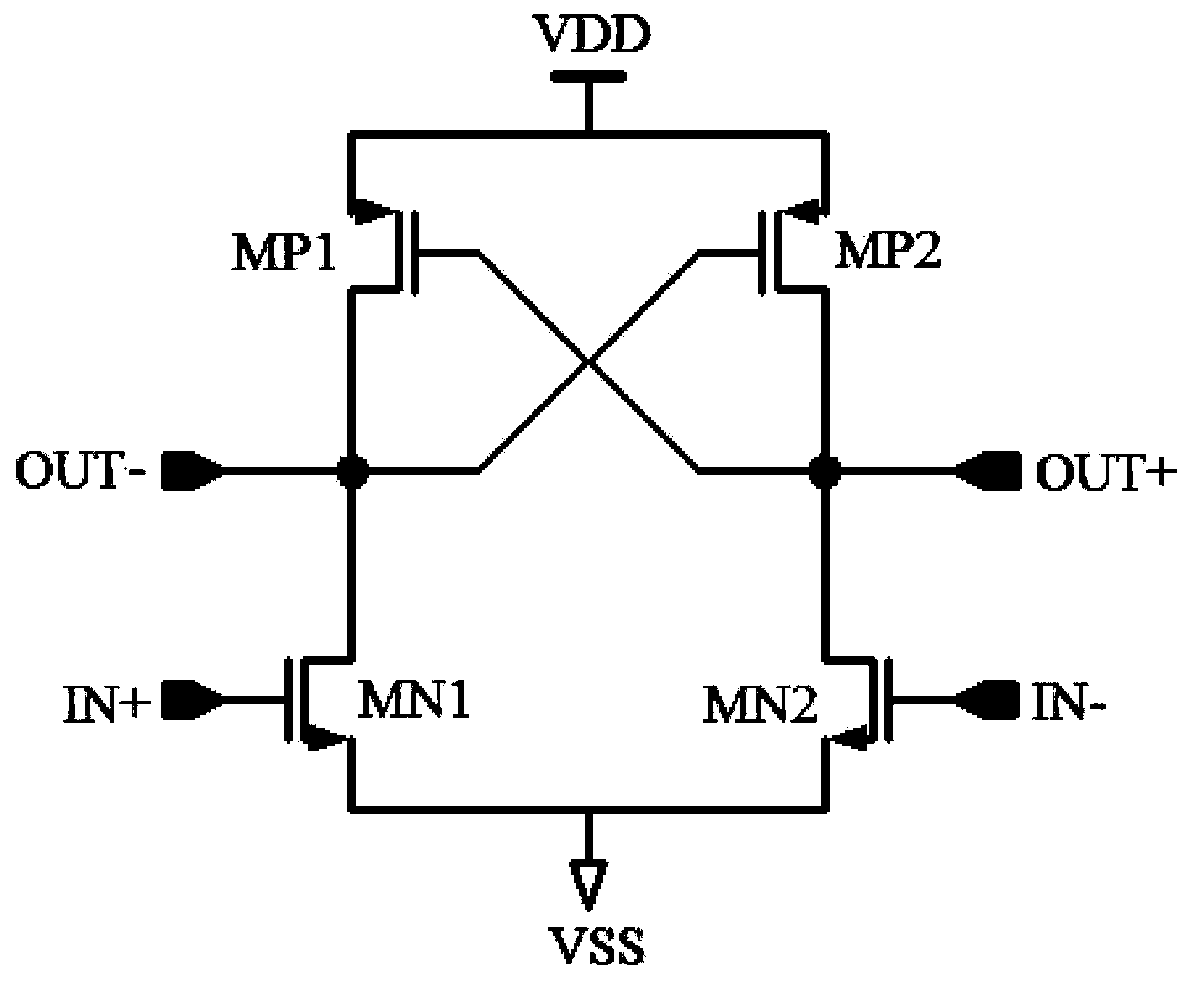
[0006] The traditional low-to-high logic level conversion circuit has the following disadvantages: when the high power supply voltage domain (that is, VDD and VSS) has been established, but the low power supply voltage domain has not yet been established (often in the low power supply voltage domain generated by the chip In the case of ), the positive input terminal IN+ and the negative input terminal IN- are logic low, so that the positive output terminal OUT+ and the negative output terminal OUT- appear in an indeterminate state, and their levels may be anywhere between VDD and VSS. level
This unsteady state may cause logical confusion in the subsequent circuits controlled by it, and may even cause large leakage in the subsequent circuits

Method used


Image

  • Low-to-high logic level conversion circuit
  • Low-to-high logic level conversion circuit
  • Low-to-high logic level conversion circuit

Examples


Embodiment Construction

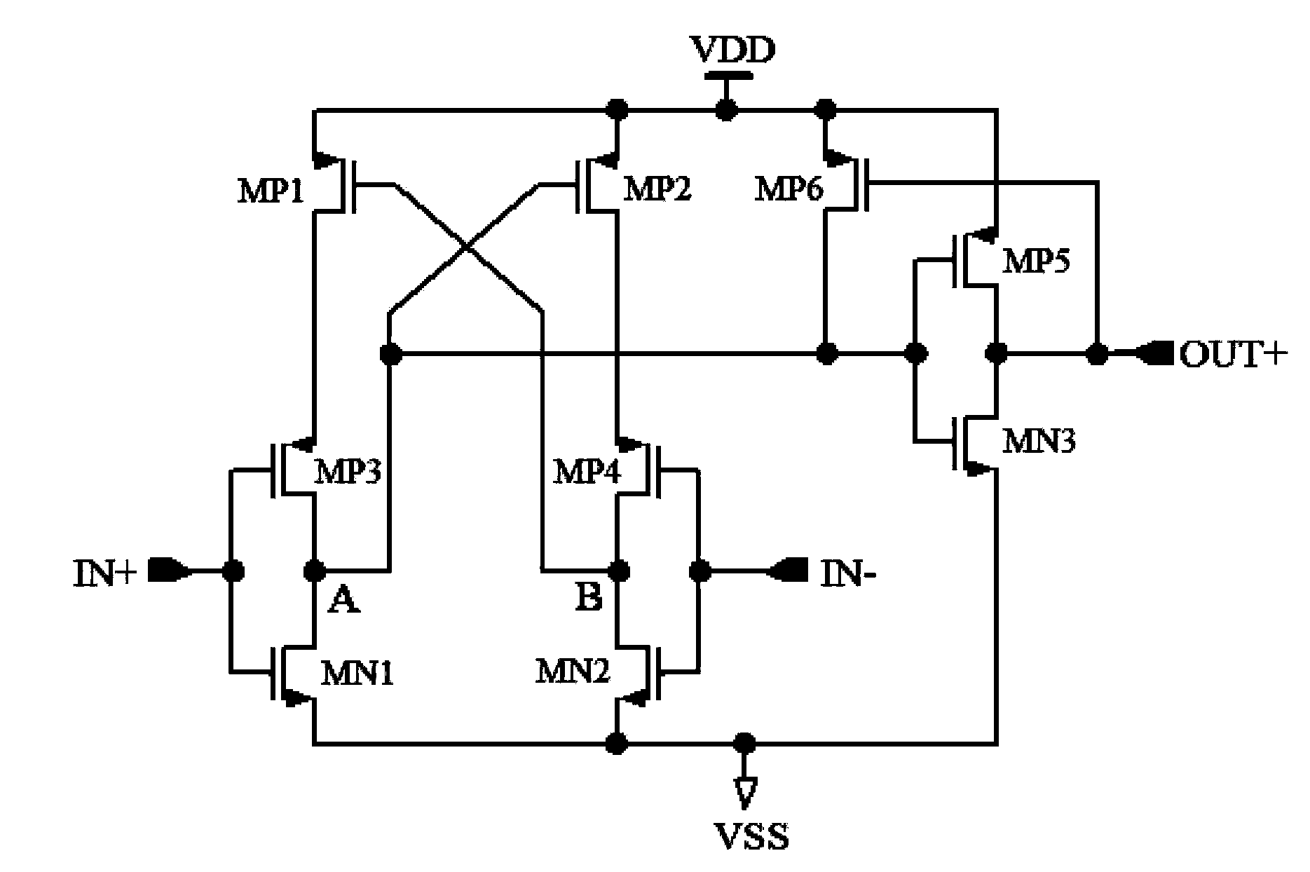
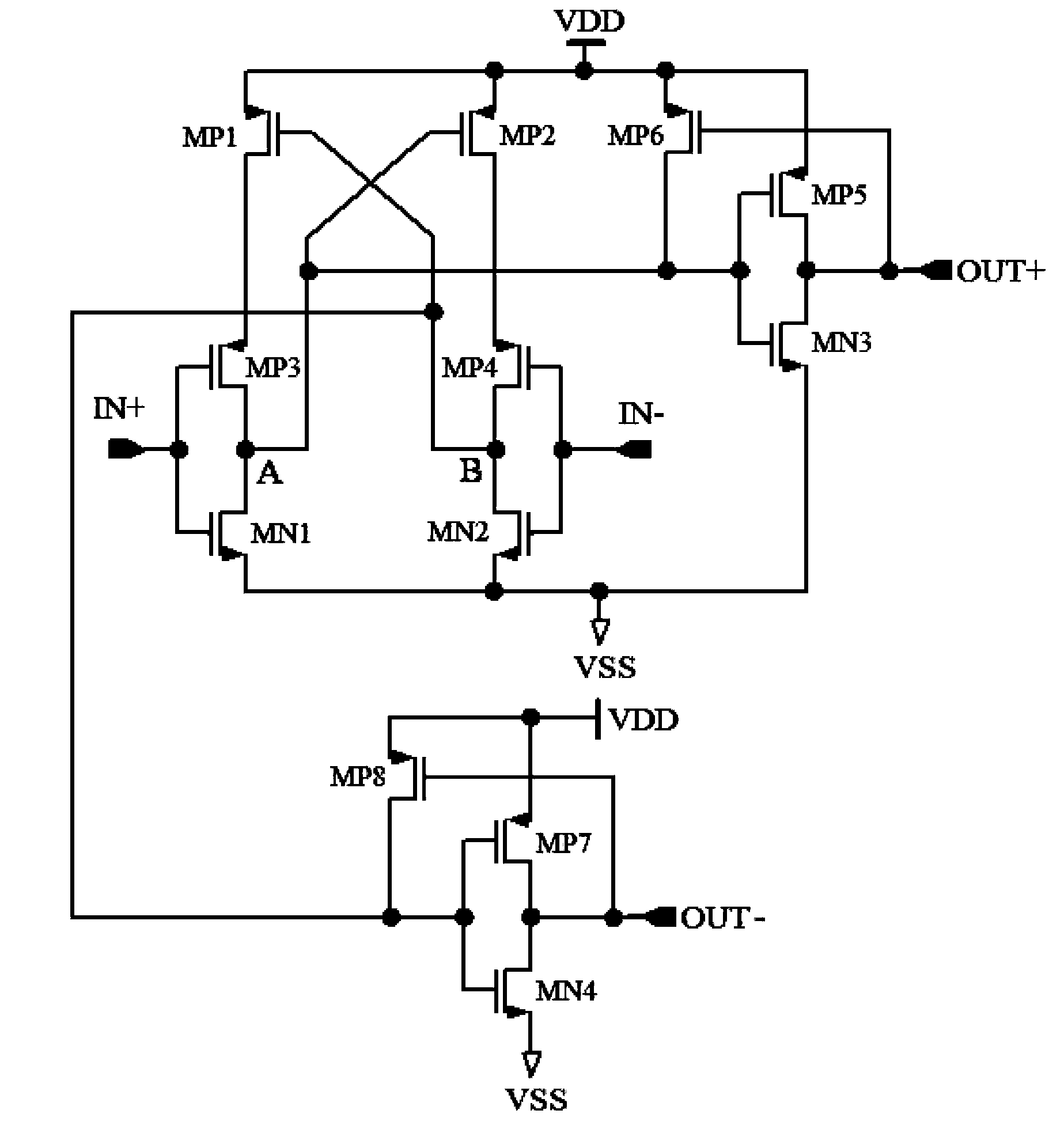
[0018] see figure 2 As shown, the conversion circuit from low to high logic level of the present invention includes in the following embodiments: a latch, a driver that helps the latch to flip quickly, an inverter, and an upper Electric self-locking feedback tube.

[0019] The input of the latch is a differential pair of transistors, and the load is a cross-coupled pair of transistors (a load transistor in the form of negative resistance).

[0020] The differential pair of transistors is composed of a first NMOS transistor and a second NMOS transistor. The sources of the first NMOS transistor and the second NMOS transistor are connected to a high-voltage logic low-level terminal, and the high-voltage logic low-level terminal is marked as VSS.

[0021] The cross-coupled pair of transistors is composed of a first PMOS transistor MP1 and a second PMOS transistor MP2, the sources of the first PMOS transistor MP1 and the second PMOS transistor MP2 are connected to a high-voltage ...


PUM


Abstract

The invention discloses a low-to-high logic level conversion circuit which comprises a latch, an actuator, a phase inverter and a feedback pipe. The input of the latch is a differential pair pipe which is formed by a first NMOS transistor and a second NMOS transistor, and a load of the latch is a cross coupling pair pipe which is formed by a first PMOS transistor and a second PMOS transistor. The actuator is arranged in the latch and helps the latch to be quickly turned over. The phase inverter and the feedback pipe are arranged at the output end of the latch, the feedback pipe enables a circuit output to be in a steady state when a low-voltage area is not powered, and when the low-voltage area is normally powered, normal work of the latch is not affected. By means of the low-to-high logic level conversion circuit, the probability that logic level is in an unsteady state when being converted to power level is avoided, and power consumption is reduced.

Description

technical field [0001] The invention relates to the field of mixed signal circuit design, in particular to a conversion circuit from low to high logic level. Background technique [0002] With the rapid development of integrated circuit technology, analog circuits and digital circuits are often integrated in the same chip. Generally, analog circuits use high power supply voltages to ensure performance, while digital circuits use low power supply voltages to save power consumption. Level translation is required when logic signals are transferred from analog to digital circuits, or vice versa. [0003] When a logic signal is transferred from a high-voltage domain to a low-voltage domain, a high-to-low logic level conversion circuit is used, usually an inverter using a low supply voltage can be implemented. However, when the logic signal is transmitted from the low-voltage domain to the high-voltage domain, the level conversion circuit is more complicated than the inverter, u...

Claims


Application Information

Patent Timeline
Patent Type & Authority Applications(China)
IPC IPC(8): H03K19/0185
Inventor 武洁苏威韩志强
Owner SHANGHAI HUAHONG INTEGRATED CIRCUIT
Learn More