
Evaporation source device

An evaporation source and crucible technology, which is applied in the field of OLED display, can solve the problems affecting the production efficiency of OLED panels, the waste of evaporation materials, and the long stabilization time of evaporation rate, so as to shorten the stabilization time, facilitate formation, increase evaporation rate and stabilize evaporation sexual effect

Inactive Publication Date: 2014-06-11
SICHUAN CCO DISPLAY TECH
View PDF5 Cites 9 Cited by
  • Summary
  • Abstract
  • Description
  • Claims
  • Application Information

AI Technical Summary

Problems solved by technology

[0010] At present, the boiling point of OLED light-emitting materials is several hundred degrees Celsius. Generally, resistance heating is used in the vacuum evaporation process. However, resistance heating has obvious disadvantages, such as long evaporation rate stabilization time, which not only causes waste of evaporation materials. And affect the production efficiency of the entire OLED panel

Method used


Image

  • Evaporation source device
  • Evaporation source device

Examples


Embodiment Construction

[0019] In order to make the object, technical solution and advantages of the present invention clearer, the present invention will be further described in detail below in conjunction with the accompanying drawings and embodiments. It should be understood that the specific embodiments described here are only used to explain the present invention, not to limit the present invention.

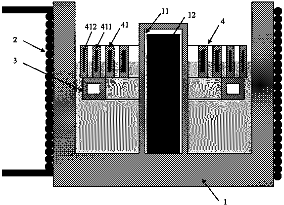
[0020] Such as figure 1 As shown, the evaporation source device of the present invention includes a crucible 1, a coil 2, a buoyancy ring 3 and an evaporation interface heating device 4:

[0021] The coil 2 surrounds the outside of the crucible 1; a cylindrical hollow protrusion 11 is provided in the middle of the crucible 1, and an iron core 12 is arranged inside the protrusion 11. When an alternating current is passed into the coil 2, an eddy current will be generated inside the iron core 12 , and then generate heat to form a heating element for induction eddy current heating. The heat heats the...


PUM


Abstract

The invention discloses an evaporation source device. The evaporation source device comprises a crucible, a coil, a buoyancy ring and an evaporation interface heating device, wherein the coil surrounds outside the crucible, a cylindrical hollow bulge is arranged in the middle of the crucible, the bulge is internally provided with an iron core, the buoyancy ring is of a hollow annular structure and sheaths on the bulge in the middle of the crucible, the evaporation interface heating device comprises a plurality of concentric annulus heating sheets, the iron flake of each annulus heating sheet is wrapped by ceramic, and the evaporation interface heating device sheaths on the bulge in the middle of the crucible and is arranged on the buoyancy ring. The evaporation source device heats by induction eddy, so that on the one hand, on even ground, stabilization time of evaporation rate can be remarkably shortened; on the other hand, the evaporation interface can be directly heated at real time so as to supplement heat taken away by evaporation, thus being beneficial to improving evaporation rate and evaporation stability and being easy to form uniform coating films.

Description

technical field [0001] The invention belongs to the technical field of OLED display, and in particular relates to a novel evaporation source device. Background technique [0002] Organic Light Emitting Diode (OLED), also known as "Organic Electroluminescent Display", is a new type of flat panel display technology with the greatest development potential after LCD and PDP. The attention of the state and enterprises is currently in the stage of rapid technological development and the gradual start of the industry. [0003] OLED has many advantages such as active light emission, fast response speed, low-voltage drive, low power consumption, all-solid-state structure, ultra-thin, wide viewing angle, and wide temperature range. It is called "dream display" in the industry and represents the current display technology. direction of development. The organic material evaporation process is a key process in the OLED production process, which has a great impact on the yield and produ...

Claims


Application Information

Patent Timeline
Patent Type & Authority Applications(China)
IPC IPC(8): C23C14/26
Inventor 潘剑白陈思敏赵芳
Owner SICHUAN CCO DISPLAY TECH
Learn More