
positive displacement pump

A technology of positive displacement pump and pump assembly, applied in the direction of pump, rotary piston pump, pump element, etc., can solve the problems of cracking of lubricating film, end-side wear, etc. Effect

Active Publication Date: 2017-06-23
PUMP TECH SOLUTIONS PS GMBH
View PDF9 Cites 0 Cited by
  • Summary
  • Abstract
  • Description
  • Claims
  • Application Information

AI Technical Summary

Problems solved by technology

However, under unfavorable operating conditions of positive displacement pumps, e.g. cold start or extreme speed gradients, when the lubrication gap between the annular spokes of the control disc and the rotor is too small, cracking of the lubricating film can occur and this can cause damage to the rotor end side wear on

Method used


Image

  • positive displacement pump
  • positive displacement pump

Examples


Embodiment Construction

[0031] The invention will be described below on the basis of a vane pump. However, the solution according to the invention is of course also suitable for roller pumps.

[0032] Vane pumps are widely known, for which reference is made to the documents mentioned at the outset, so only the components that are relevant to the invention will be discussed in detail below.

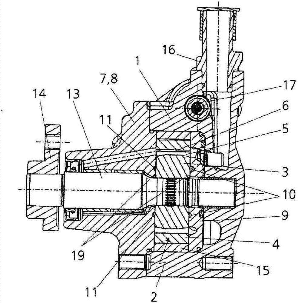
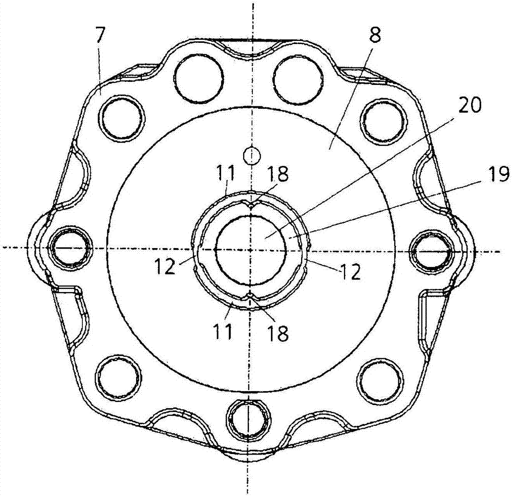
[0033] A pump assembly 2 is installed inside the housing 1 , which includes a rotor 3 , a cam ring 4 surrounding the rotor and a plurality of working slides 5 distributed on the circumference of the rotor 3 . A working chamber 6 separated by a working slide 5 is formed between the cam ring 4 and the rotor 3 . Control discs 8 and 9 are arranged on both end faces of the rotor. The control panel 8 is integrated into the housing cover 7 or the housing cover.

[0034] Two opposing kidney-shaped supply channels 10 are arranged in the control disk 9 . In the same way, the control disk 8 as housing cover 7 has two bl...


PUM


Abstract

The invention relates to a displacement pump for delivering pressure medium to a load, in particular to a power steering system for a motor vehicle. A pump unit (2) comprising a rotor (3), a cam ring (4) and working slides (5) is arranged inside the housing (1), which is axially divided on one side by a The lid (7) is closed. Formed between the cam ring (4) and the rotor (3) are working chambers (6) separated by working slides (5), which are delimited in the axial direction by a control disk (9). The kidney-shaped supply channels ( 10 , 11 ) for supplying the working slide ( 5 ) and the working chamber ( 6 ) with oil are formed in the end face of the control disk ( 9 ) facing the rotor ( 3 ). There are annular spokes ( 19 ) in the kidney-shaped supply channels ( 10 , 11 ) and in the through-hole ( 20 ) for the drive shaft ( 13 ). At least one of the kidney-shaped supply channels (10, 11) is provided with at least one oil groove (18). The at least one oil groove (18) is arranged to protrude at least partially into the spoke (19).

Description

technical field [0001] The invention relates to a displacement pump for delivering pressure medium to a load, in particular to a power steering system for a motor vehicle. Background technique [0002] Displacement pumps in the form of vane pumps or roller pumps are known, for example, from DE 199 09 963 B4, DE 10 2006 052 996 A1 or DE 102 29 809 A1. [0003] Positive displacement pumps have a pump assembly with a rotor, a cam ring and a plurality of working slides, for example vanes or rollers, in which a plurality of individual working chambers are formed. The rotor is delimited by the control disk on both end faces or in the axial direction. For this purpose, the control panel can also be integrated on one side in the housing cover of the housing or be formed by the housing cover. [0004] The rotors are delimited on both end sides by control disks which each have an annular spoke between the kidney-shaped supply channel for the blades or rollers and the through-opening...

Claims


Application Information

Patent Timeline
Patent Type & Authority Patents(China)
IPC IPC(8): F01C21/08F01C21/10F04C2/344F04C14/06F04C15/00F04C14/28
CPCF01C21/0854F01C21/108F04C2/344F04C14/06F04C14/28F04C15/0088
Inventor C·耶格尔R·迈尔
Owner PUMP TECH SOLUTIONS PS GMBH
Learn More