A hybrid ignition method for hid lamp electronic ballast
An electronic ballast and electric current technology, applied in the direction of electric light sources, electrical components, lighting devices, etc., can solve the problems of difficult to reliably start high-power metal halide lamps, high operating frequency of electronic ballasts, narrow adjustable range of intensity, etc. problems, to achieve the effect of improving ignition reliability, preventing overcurrent, and improving the reliability of the whole machine
- Summary
- Abstract
- Description
- Claims
- Application Information
AI Technical Summary
Problems solved by technology
Method used
Image

Examples
Embodiment 1
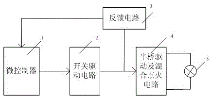
[0037] like Figure 5 and Figure 9 As shown, the circuit connection description of this embodiment is the same as that in the invention patent with the patent number "201310008933.0" figure 2 and Image 6 , the difference is that the two ends of the patented HID lamp 5 of the present invention are connected in parallel with the resonant capacitor C5.
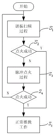
[0038] like Figure 5 In the illustrated embodiment, the software workflow of the patented hybrid ignition method of the present invention is as follows:
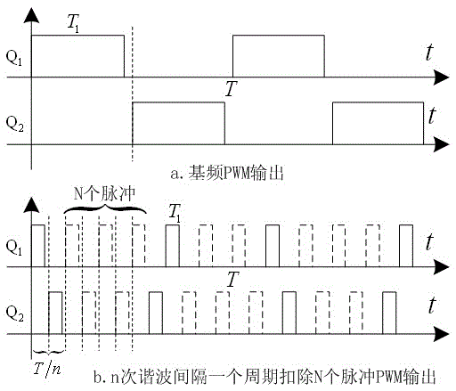
[0039] S1. The microcontroller 1 generates a PWM pulse signal that drives the power switch tubes Q1 and Q2, and the resonant frequency sweeping process starts;
[0040]S2. Detect the current flowing through R3 through the pulse feedback circuit 3 to determine whether the ignition is successful; if successful, go to step S5, if unsuccessful, go to step S3;
[0041] S3. The microcontroller 1 generates a PWM pulse signal that drives the power switch tube Q2, and the DC lo...
Embodiment 2
[0050] like Image 6 and Figure 10 As shown, the specific connection method of the circuit is as follows: capacitor C1 and resistor R1 are connected in parallel, one end of the parallel connection is connected to one end of inductor L1 and one end of HID lamp 5, and the other end is connected to VDC; one end of the inductor L21 is connected to one end of the inductor L22, the silicon One end of the two-terminal element SIDAC is connected to one end of the lamp 5, the other end of the inductor L21 is connected to one end of the power switch Q1 and one end of the power switch Q2, the other end of the inductor L22 is connected to one end of the capacitor C2, and the silicon two-terminal element The other end of the SIDAC is connected to the other end of the resistor R2 and the other end of the capacitor C2; the other end of the power switch Q1 is connected to VDC, the other end of the power switch Q2 is connected to one end of the resistor R3, and the other end of the resistor R...
Embodiment 3
[0052] like Figure 7 and Figure 11 As shown, compared with Embodiment 2, the ignition trigger device is changed, and the thyristor trigger circuit is used instead of the silicon two-terminal element SIDAC trigger. The thyristor trigger circuit includes: capacitor C21, resistor R4, resistor R5, low-voltage silicon two-terminal element D303, and thyristor SCR. The circuit ignition trigger works as follows: when the ignition circuit is working, VDC forms a loop through the resistors R1, R2, R3, R4, R5, the inductors L1, L21 and the power switch tube Q2. When the voltage on the resistor R5 exceeds the trigger voltage of D303 ( 28V~32V), D303 is turned on, thereby triggering the thyristor SCR, that is, replacing the function of the silicon two-terminal element SIDAC in Example 2. The working principle of other parts is the same as that of Embodiment 2.
PUM
 Abstract
Description
Claims
Application Information
 - Generate Ideas
- Intellectual Property
- Life Sciences
- Materials
- Tech Scout
- Unparalleled Data Quality
- Higher Quality Content
- 60% Fewer Hallucinations
Browse by: Latest US Patents, China's latest patents, Technical Efficacy Thesaurus, Application Domain, Technology Topic, Popular Technical Reports.
© 2025 PatSnap. All rights reserved.Legal|Privacy policy|Modern Slavery Act Transparency Statement|Sitemap|About US| Contact US: help@patsnap.com