
Field emission light source assembly

A light source component and field emission technology, applied in the field of lighting, can solve problems such as high requirements for preparation technology, complicated process, and increased cost, and achieve the effects of easy portability and transportation, simplified preparation process, and reduced volume

Inactive Publication Date: 2014-06-04
OCEANS KING LIGHTING SCI&TECH CO LTD +2
View PDF0 Cites 2 Cited by
  • Summary
  • Abstract
  • Description
  • Claims
  • Application Information

AI Technical Summary

Problems solved by technology

However, manufacturing a field emission light source with a large light-emitting surface requires higher preparation technology and a complicated process, which increases the cost
Moreover, the material of the field emission light source is generally fragile, and the field emission light source with a large light-emitting area is easily damaged during transportation engineering, so it is not easy to carry and transport

Method used


Image

  • Field emission light source assembly
  • Field emission light source assembly
  • Field emission light source assembly

Examples


Embodiment Construction

[0029] In order to facilitate the understanding of the present invention, the present invention will be described more fully below with reference to the associated drawings. Preferred embodiments of the invention are shown in the accompanying drawings. However, the present invention can be embodied in many different forms and is not limited to the embodiments described herein. On the contrary, these embodiments are provided to make the understanding of the disclosure of the present invention more thorough and comprehensive.

[0030] It should be noted that when an element is referred to as being “fixed” to another element, it can be directly on the other element or there can also be an intervening element. When an element is referred to as being "connected to" another element, it can be directly connected to the other element or intervening elements may also be present.

[0031] Unless otherwise defined, all technical and scientific terms used herein have the same meaning as...


PUM


Abstract

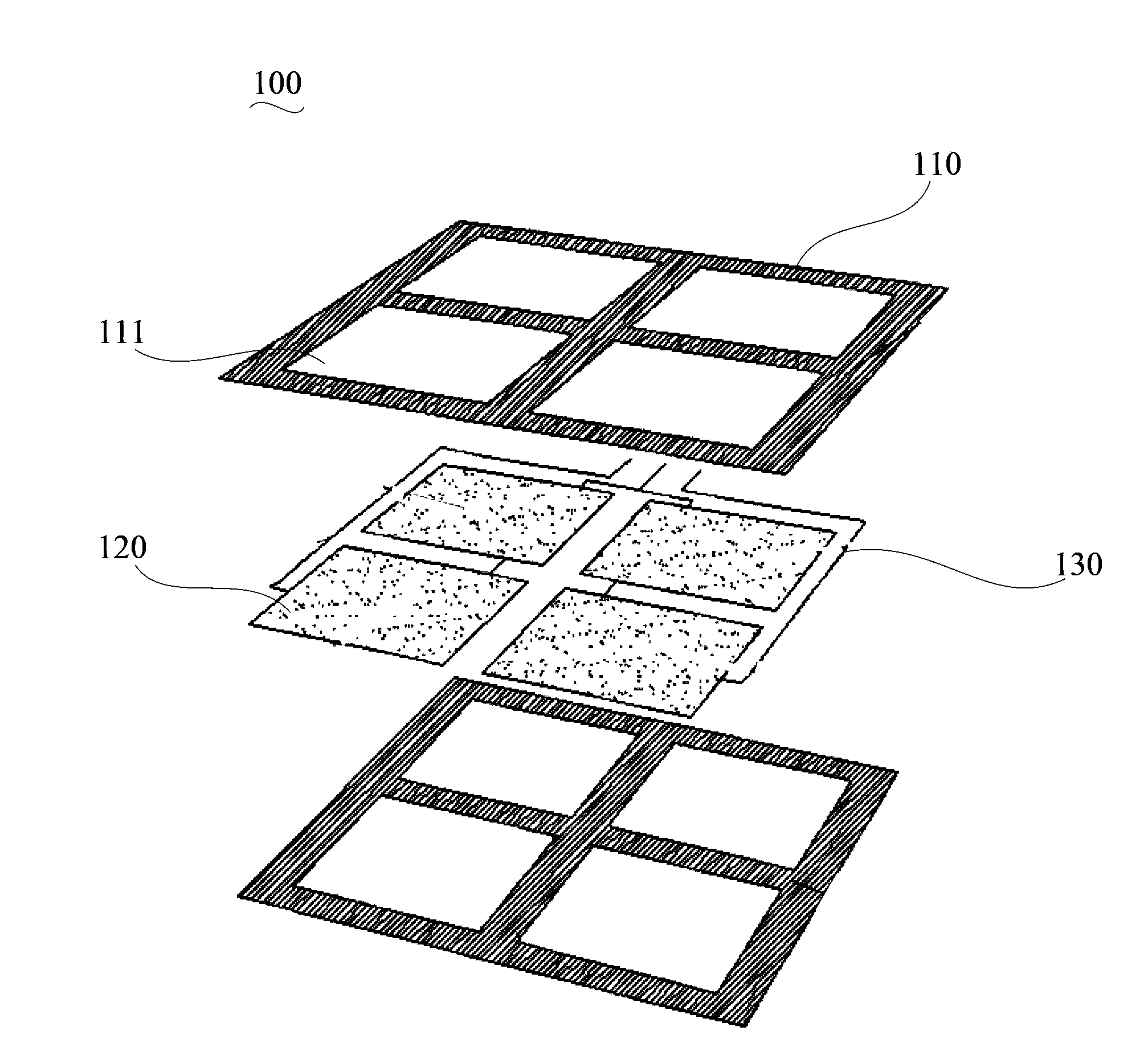
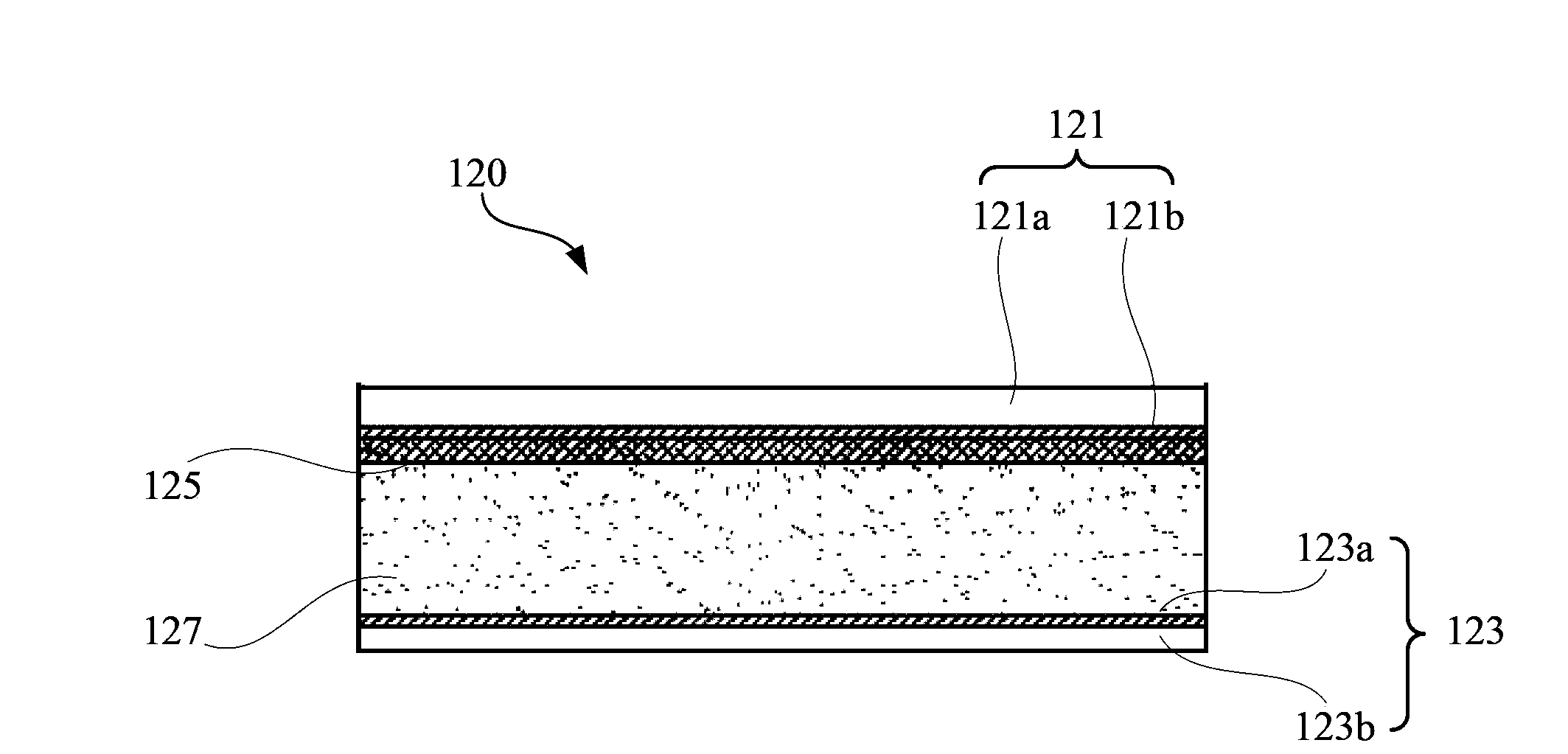
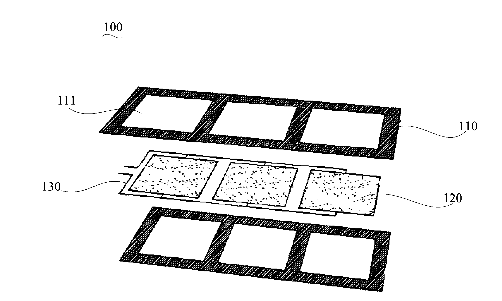
The invention provides a field emission light source assembly comprising a flexible substrate and multiple field emission light sources which are fixed on the flexible substrate according to the preset arrangement sequence. When the field emission light source assembly needs to be applied to a lamp, the flexible substrate is unfolded so that the multiple field emission light sources are arranged in the same plane, and thus the light emission surface of the overall field emission light source assembly is enlarged. The size of the light emission surface of the field emission light source assembly equals to the sum of the size of the light emission surfaces of the multiple field emission light sources so that the size of the light emission surface of the single field emission light source does not need to be quite large in manufacturing, and thus the preparation process is simplified and cost is effectively reduced. Besides, the substrate is bent during transportation so that the multiple field emission light sources are mutually overlapped, and thus volume of the aforementioned field emission light source assembly is reduced, and carrying and transportation are facilitated.

Description

technical field [0001] The invention relates to lighting technology, in particular to a field emission light source assembly. Background technique [0002] As a new type of light source, the field emission light source has the advantages of uniform light emission, low heat generation, and large light emission angle. At present, field emission light sources have been widely used in the lighting field. [0003] Flat panel field emission light source is the most common field emission lighting source. The brightness and the uniformity of the light emitted by the flat-plate field emission light source are determined by the light-emitting area of ​​the field emission light source. The larger the light-emitting area, the higher the brightness and the more uniform the light distribution. Therefore, a high-quality flat field emission light source generally has a larger light emitting surface. However, manufacturing a field emission light source with a large light-emitting surface...

Claims


Application Information

Patent Timeline
IPC IPC(8): H01J61/06H01J61/02
Inventor 周明杰梁艳馨陈贵堂
Owner OCEANS KING LIGHTING SCI&TECH CO LTD
Learn More