
Heat flow switch for controlling heat tube conduction

A heat pipe and switch technology, applied in the field of heat flow switches for controlling heat pipe conduction, can solve the problems that the working temperature of the high temperature part fails to meet the working requirements, the normal use of the equipment in the high temperature part is affected, and the heat conduction efficiency of the heat pipe is low. Good control, reasonable design effect

Inactive Publication Date: 2014-06-04
陕西科林能源发展股份有限公司
View PDF0 Cites 2 Cited by
  • Summary
  • Abstract
  • Description
  • Claims
  • Application Information

AI Technical Summary

Problems solved by technology

But the current problem is that the heat pipe is an uninterrupted process when transferring heat from the high temperature part to the low temperature part, and in the above occasions we only need to transfer the excess heat, that is, when the temperature is higher than a certain temperature Carry out the heat transfer of the heat pipe, and the uninterrupted heat transfer will cause the working temperature of the high temperature part to fail to meet the working requirements, which will affect the normal use of the high temperature part of the equipment
[0003] We have also tried adding valves to the heat pipes, but conventional valve devices are inconvenient to control, and when the material and structure of the valves are different from those of the heat pipes, the heat transfer efficiency of the heat pipes will be low

Method used


Image

  • Heat flow switch for controlling heat tube conduction
  • Heat flow switch for controlling heat tube conduction
  • Heat flow switch for controlling heat tube conduction

Examples


Embodiment Construction

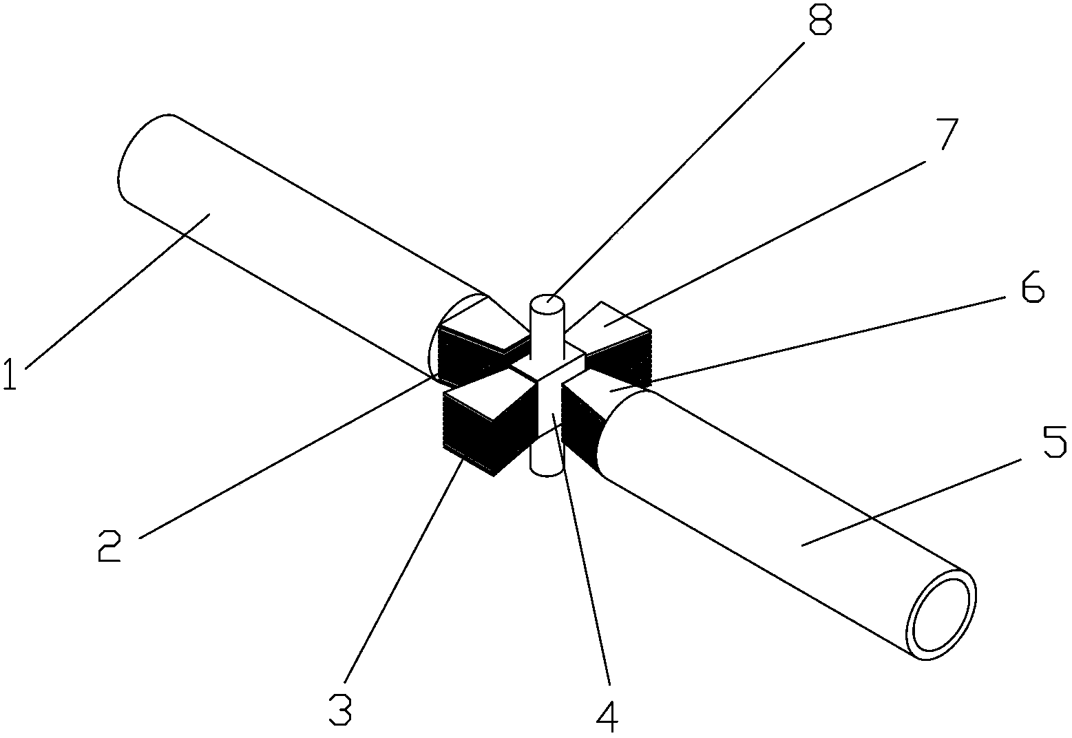
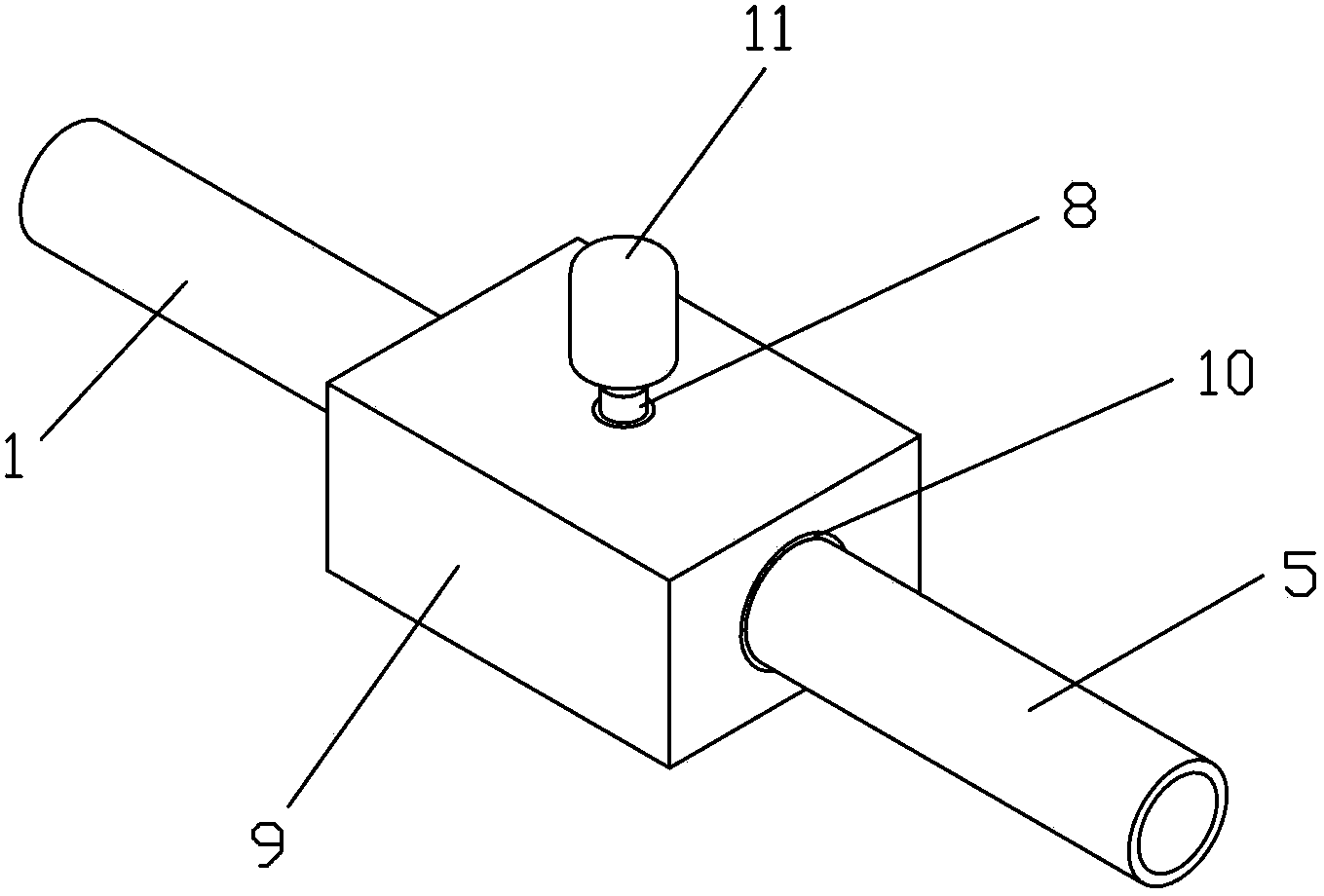
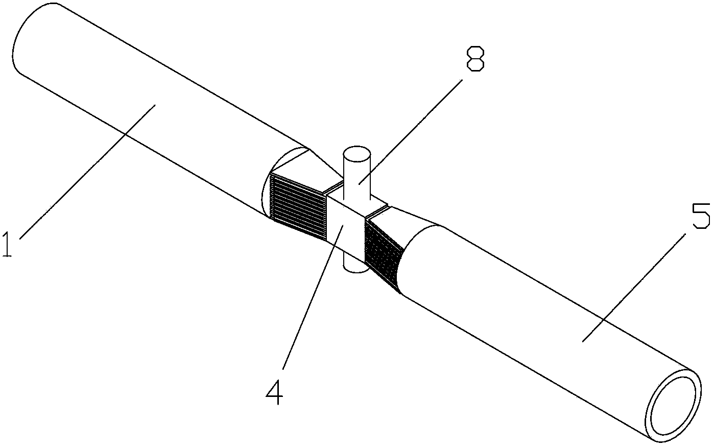
[0023] Such as Figure 1 to Figure 3 As shown, the present invention includes a switch housing 9, a switch motor 11, a first heat transfer fin group 2 installed at the end of the first heat pipe 1 and a second heat transfer fin group 6 installed at the end of the second heat pipe 5, and The connection body 4 arranged between the first heat transfer fin group 2 and the second heat transfer fin group 6 and the switch shaft 8 fixedly installed on the connection body 4, the first heat pipe 1 and the second heat pipe 5 The ends all extend into the inside of the switch housing 9, the ends of the first heat pipe 1 and the second heat pipe 5 are arranged oppositely, and the first heat transfer fin group 2 and the second heat transfer fin group 6 are composed of a plurality of Sheets with a certain thickness are arranged at intervals, one side of the connecting body 4 is equipped with a third heat transfer fin group 3 engaged with the first heat transfer fin group 2, and the other side...


PUM


Abstract

The invention discloses a heat flow switch for controlling heat tube conduction. The heat flow switch comprises a switch shell, a switch motor, a first heat conduction fin set installed at the tail end of a first heat tube, a second heat conduction fin set installed at the tail end of a second heat tube, a connecting body arranged between the first heat tube fin set and the second heat conduction fin set and a switch shaft installed on the connecting body. The tail end of the first heat tube and the tail end of the second heat tube stretch into the switch shell respectively, the tail end of the first heat tube and the tail end of the second heat tube are arranged oppositely, a third heat conduction fin set meshed with the first heat conduction fin set is installed on one side of the connecting body, a fourth heat conduction fin set meshed with the second heat conduction fin set is installed on the other side of the connecting body, the first heat conduction fin set, the second heat conduction fin set, the connecting body, the third heat conduction fin set and the fourth heat conduction fin set are all located inside the switch shell, the switch shaft is installed on the switch shell, and the upper end of the switch shaft is connected with the switch motor. The heat flow switch can well control heat tube conduction and cannot affect the heat tube transmission efficiency.

Description

technical field [0001] The invention relates to a heat flow switch, in particular to a heat flow switch for controlling heat pipe conduction. Background technique [0002] A heat pipe is a device that transfers energy from an evaporator that absorbs heat to an evaporator that releases heat by evaporating and condensing a working fluid contained therein. Due to the high heat conduction efficiency and no noise of heat pipes, the application of heat pipes has become more and more popular. In some industrial production fields, heat pipes transfer the excess heat generated by some equipment to places that need to be heated. Such applications can make full use of resources. It has high environmental benefit and energy saving effect. But the current problem is that the heat pipe is an uninterrupted process when transferring heat from the high temperature part to the low temperature part, and in the above occasions we only need to transfer the excess heat, that is, when the tempera...

Claims


Application Information

Patent Timeline
Patent Type & Authority Applications(China)
IPC IPC(8): F28D15/06
Inventor 杨向民
Owner 陕西科林能源发展股份有限公司
Learn More