
Automatic temperature control device for shoe-drying panel

A technology for panels and baking shoes, applied in household cleaning devices, non-electric variable control, temperature control, etc., can solve the problems of nowhere to bake wet shoes, not being able to bake, and discounts on the baking effect of wet shoes.

Inactive Publication Date: 2014-06-04
王志
View PDF7 Cites 1 Cited by
  • Summary
  • Abstract
  • Description
  • Claims
  • Application Information

AI Technical Summary

Problems solved by technology

[0002] In rainy days, continuous rainy days, or rainy and snowy days, once the shoes get wet, especially if the shoes are soaked by children playing with water, it will be very uncomfortable to wear wet shoes the next day
All kinds of shoe dryers, shoe dryers, shoe dryers, shoe warmers and other products on the market are almost two shoe dryers with a wire for inserting into the upper part of the shoe respectively. (The front part of the shoe), if the shoes are all wet, the second half of the shoes can't be baked at all, what's more troublesome is that it can only bake one pair of shoes at a time, and there is nowhere to bake the wet shoes of the family
In addition, there are problems in the use and maintenance of the shoe dryer. When using it, special attention should be paid to prevent dust or debris from blocking the cooling holes of the shoe dryer. Otherwise, most of the heat emitted by the shoe dryer will be enclosed in the shoe dryer, resulting in wet shoes drying. The roasting effect is greatly reduced, and it is easy to bury fire hazards

Method used


Image

  • Automatic temperature control device for shoe-drying panel

Examples


Embodiment Construction

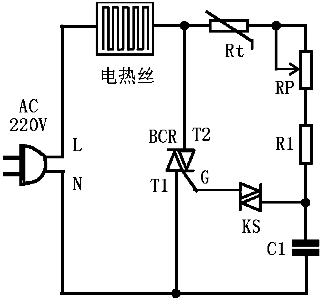
[0012] According to attached figure 1 The working principle diagram and description of the circuit of the automatic temperature control device for the baking shoe panel shown, and the connection relationship between the components in each part of the circuit described in the summary of the invention, as well as the technical parameter requirements and requirements of the components described in the implementation mode The main points of making the circuit can be implemented to realize the present invention, and the related technologies of the present invention will be further described below in conjunction with the embodiments.

[0013] Technical parameters and selection requirements of components

[0014] BCR is a bidirectional thyristor, and the selected model is 3CTSI;

[0015] KS is a bidirectional trigger diode, the selected model is 2CTS, or BCR3AM;

[0016] The resistance of the thermistor Rt is 5.1KΩ, and the thermistor Rt is required to use a positive temperature co...


PUM


Abstract

The invention discloses an automatic temperature control device for a shoe-drying panel. The automatic temperature control device is characterized in that the automatic temperature control device comprises a 220 V alternating-current power supply, an RC phase-shift circuit, a double-direction silicon controlled rectifier control circuit and an electric heating wire. The RC phase-shift circuit is composed of a linear potentiometer RP, a thermistor Rt, a resistor R1, a capacitor C1 and a diode AC switch KS; in the double-direction silicon controlled rectifier control circuit, the second anode T2 of a double-direction silicon controlled rectifier BCR T2 is connected with one end of the electric heating wire, the other end of the electric heating wire is connected with the live-line end L of the 220 V alternating-current power supply, and the first anode T1 of the double-direction silicon controlled rectifier BCR T2 is connected with the null-line end N of the 220 V alternating-current power supply. Different from shoe drying modes of traditional shoe-drying devices, an insulating board is paved with the electric heating wire, the surface temperature of the shoe-drying panel is adjusted by the linear potentiometer, four or more pairs of shoes can be dried by the shoe-drying panel at the same time, the best shoe drying and dehumidification effect can be achieved for any type of shoes, and the automatic temperature control device is very convenient to use.

Description

technical field [0001] The invention belongs to the technical field of electronics and temperature control, and relates to an automatic temperature control device for a shoe baking panel. Background technique [0002] In cloudy and rainy days, continuous rainy days or rainy and snowy days, once the shoes get wet, especially if the shoes are soaked by children playing with water, it will be very uncomfortable to wear wet shoes the next day. All kinds of shoe dryers, shoe dryers, shoe dryers, shoe warmers and other products on the market are almost two shoe dryers with a wire for inserting into the upper part of the shoe respectively. (The front part of the shoe), if the shoes are all wet, the second half of the shoes can't be baked at all. What's more troublesome is that it can only bake one pair of shoes at a time, and there is nowhere to bake the family's wet shoes. In addition, there are problems in the use and maintenance of the shoe dryer. When using it, special attenti...

Claims


Application Information

Patent Timeline
IPC IPC(8): A47L23/20G05D23/24
Inventor 王志
Owner 王志
Learn More