
Portable full automatic resistance spot welding ultrasonic detecting instrument and detecting method

A technology of resistance spot welding and ultrasonic, which is applied in the direction of using sound wave/ultrasonic wave/infrasonic wave to analyze solids, etc. It can solve the problems of no ultrasonic non-destructive testing equipment, lack of automation, intelligence, quantification, and difficulty in meeting industrial production. Lightweight, cost-effective, good contact coupling effect

Inactive Publication Date: 2014-05-28
JILIN UNIV
View PDF4 Cites 35 Cited by
  • Summary
  • Abstract
  • Description
  • Claims
  • Application Information

AI Technical Summary

Problems solved by technology

[0005] The present invention mainly solves the problem that spot welding quality detection mainly relies on water immersion manual operation at the present stage, and there is no suitable ultrasonic nondestructive testing equipment, especially the lack of automatic, intelligent and quantitative portable ultrasonic testing equipment, which is difficult to meet To meet the needs of modern industrial production, a portable resistance spot welding automatic ultrasonic detector and detection method for online real-time automatic quality inspection of resistance spot welding are provided.

Method used

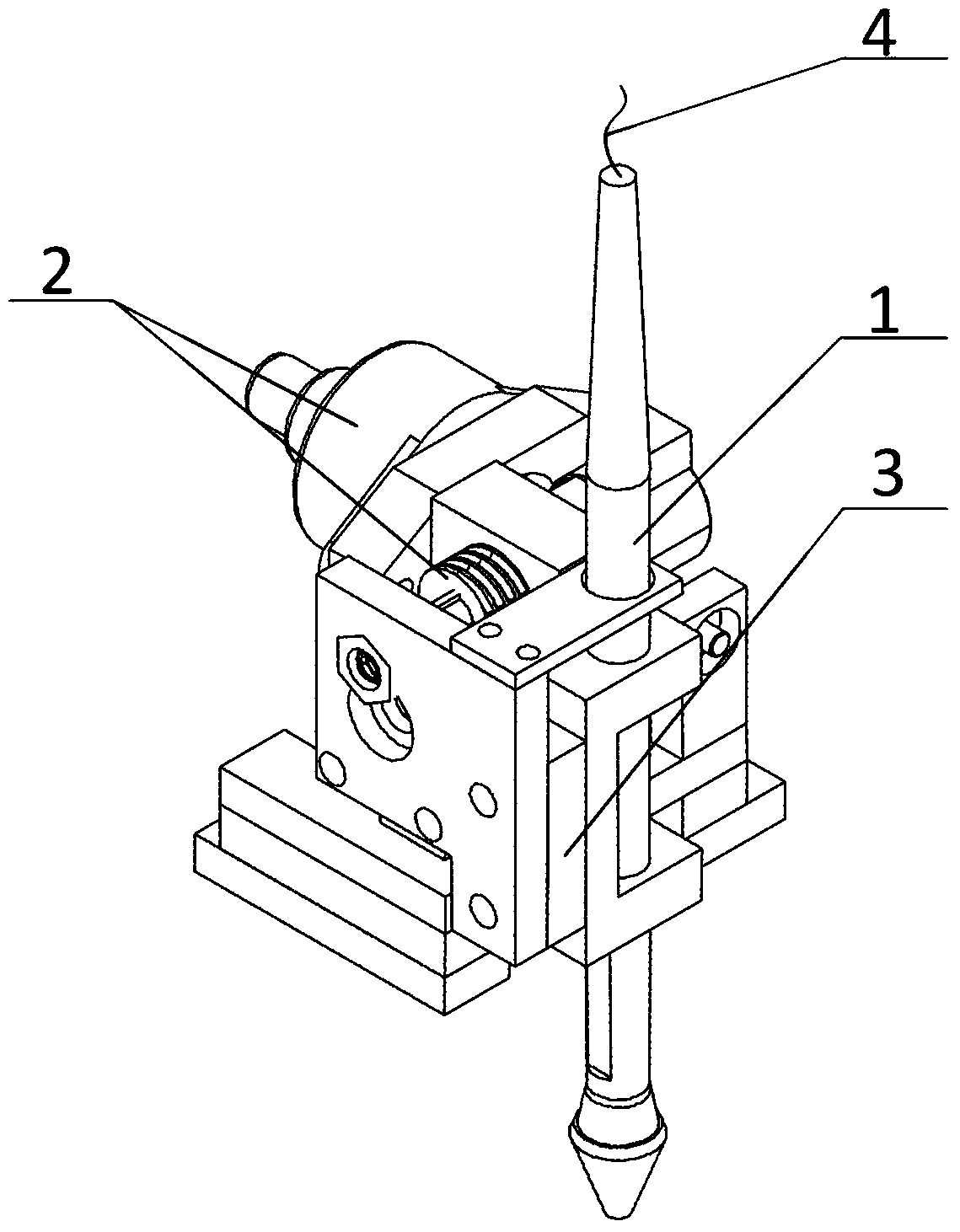
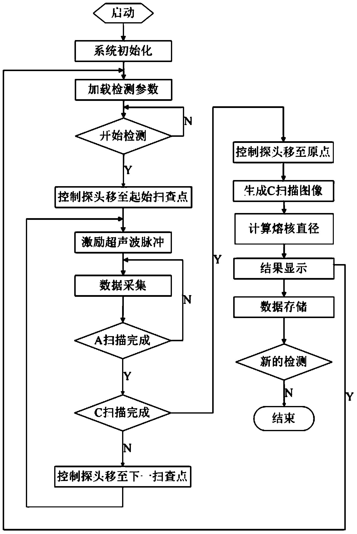

Image

  • Portable full automatic resistance spot welding ultrasonic detecting instrument and detecting method
  • Portable full automatic resistance spot welding ultrasonic detecting instrument and detecting method
  • Portable full automatic resistance spot welding ultrasonic detecting instrument and detecting method

Examples


Embodiment Construction

[0035] In this embodiment, the schematic diagram of the scanning path of the ultrasonic probe to the spot welding joint is as follows: Figure 4 shown;

[0036] The present invention carries out the method for ultrasonic detection to the spot welding joint quality and comprises the following steps:

[0037] Step 1: After the detector is started, first load the system settings such as ultrasonic probe parameters, scanning parameters, and signal preprocessing parameters. After receiving the start detection command, move the probe to the center of the spot welding spot through the motion control module as the initial scan point. Determine the size of the rectangular scanning area according to the specific spot welding process conditions to ensure that the scanning area size is larger than the spot welding spot size. In this embodiment, the stainless steel spot welding with a plate thickness combination of 2+2mm is selected as the sample to be tested, and the rectangular plane T...


PUM


Abstract

The invention relates to a portable full automatic resistance spot welding ultrasonic detecting instrument and a detecting method. The portable full automatic resistance spot welding ultrasonic detecting instrument comprises an industrial computer, an ultrasonic probe, an ultrasonic detecting module integrated in an IPC (Industrial Personal Computer), a compact-type two-dimension mechanical scanning motion module, and an ultrasonic analyzing module, wherein the ultrasonic detecting module comprises an ultrasonic pulse radiating circuit, an ultrasonic receiving circuit and an A / D conversion circuit; the compact-type two-dimension mechanical scanning motion module comprises a micro-scale linear motor, a driver, a motion control card, and a self-adaption profile-followed device; the ultrasonic analyzing module comprises a data and image processing module, a database storage module, and a manual playback and analysis module. Functions such as self-adaption scanning and detecting to the resistance spot welding joint surface, automatic generation of a C scanning image, and quantitive calculation of nugget diameter of the ultrasonic probe in the situation of non-water immersion are realized; compared with the prior art, the portable full automatic resistance spot welding ultrasonic detecting instrument and the detecting method have the advantages of simplicity in operation, portability, reliability, strong anti-jamming capability, high detection and analyzing speed and the like.

Description

technical field [0001] The invention relates to a portable full-automatic ultrasonic detector for resistance spot welding and a detection method, which are ultrasonic detectors for realizing automatic, intelligent and quantitative non-destructive testing of resistance spot welding. Background technique [0002] Resistance spot welding is an efficient and economical welding method for joining sheet metal and is widely used in modern manufacturing industries. The quality of resistance spot welding directly affects the reliability of the welded structure and even the performance of the entire product. However, during the spot welding process, since the nugget formation and growth process are in a closed state, they cannot be directly observed, and the nucleation time is extremely short. Short, short-term fluctuations in welding parameters will cause more serious defects such as spatter, virtual welding, and desoldering, so the detection of resistance spot welding quality is of ...

Claims


Application Information

Patent Timeline
IPC IPC(8): G01N29/06
Inventor 徐国成刘静谷晓鹏周广浩
Owner JILIN UNIV
Learn More