
Air-conditioning system

An air-conditioning system and interface technology, which can be applied to compressors with reversible cycles, lighting and heating equipment, fluid circulation arrangements, etc. Effectiveness of utilization, improved comfort

Active Publication Date: 2014-05-28
GREE ELECTRIC APPLIANCES INC
View PDF6 Cites 6 Cited by
  • Summary
  • Abstract
  • Description
  • Claims
  • Application Information

AI Technical Summary

Problems solved by technology

In the sensible heat load, the heat that could have been discharged by a high-temperature cold source is shared with a 5-7°C low-temperature cold source for processing with dehumidification, resulting in a waste of energy utilization grade
Moreover, although the humidity of the air after condensation and dehumidification meets the requirements, the temperature is too low in some occasions, so the air has to be reheated to meet the requirements of the air supply temperature, resulting in further waste and loss.
[0003] The air-conditioning system with independent temperature and humidity control in the prior art generally uses two independent cold water air-conditioning systems to produce cold water at a low temperature of about 7°C and cold water at a temperature of about 18°C. The system cost is high and the power consumption is large.
Even though there are some systems that solve independent control of temperature and humidity through a set of air conditioning systems, their functions are relatively single, and they can only realize the cooling mode of air conditioning, which is difficult to meet people's requirements for modern air conditioning

Method used


Image

  • Air-conditioning system
  • Air-conditioning system
  • Air-conditioning system

Examples


no. 1 example

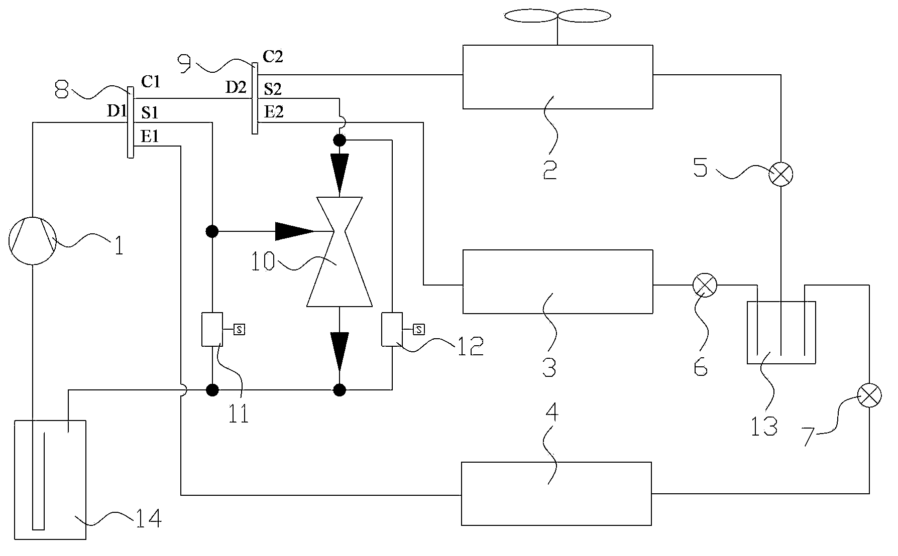
[0033] like figure 1 As shown, the air conditioning system of the first embodiment of the present invention includes a compressor 1 , a first four-way valve 8 , a second four-way valve 9 , a condenser 2 , a high temperature heat exchanger 3 , a low temperature heat exchanger 4 , and an ejector 10 , a first throttling device 5 , a second throttling device 6 , a third throttling device 7 , a first solenoid valve 11 and a second solenoid valve 12 .

[0034] The first port D1 of the first four-way valve 8 is communicated with the discharge end of the compressor 1, the second port C1 of the first four-way valve 8 is communicated with the first port D2 of the second four-way valve 9, and the first four-way valve The third port S1 of the valve 8 communicates with the injection port of the injector 10 , and the fourth port E1 of the first four-way valve 8 communicates with one end of the low temperature heat exchanger 4 .

[0035] The second port C2 of the second four-way valve 9 com...

no. 2 example

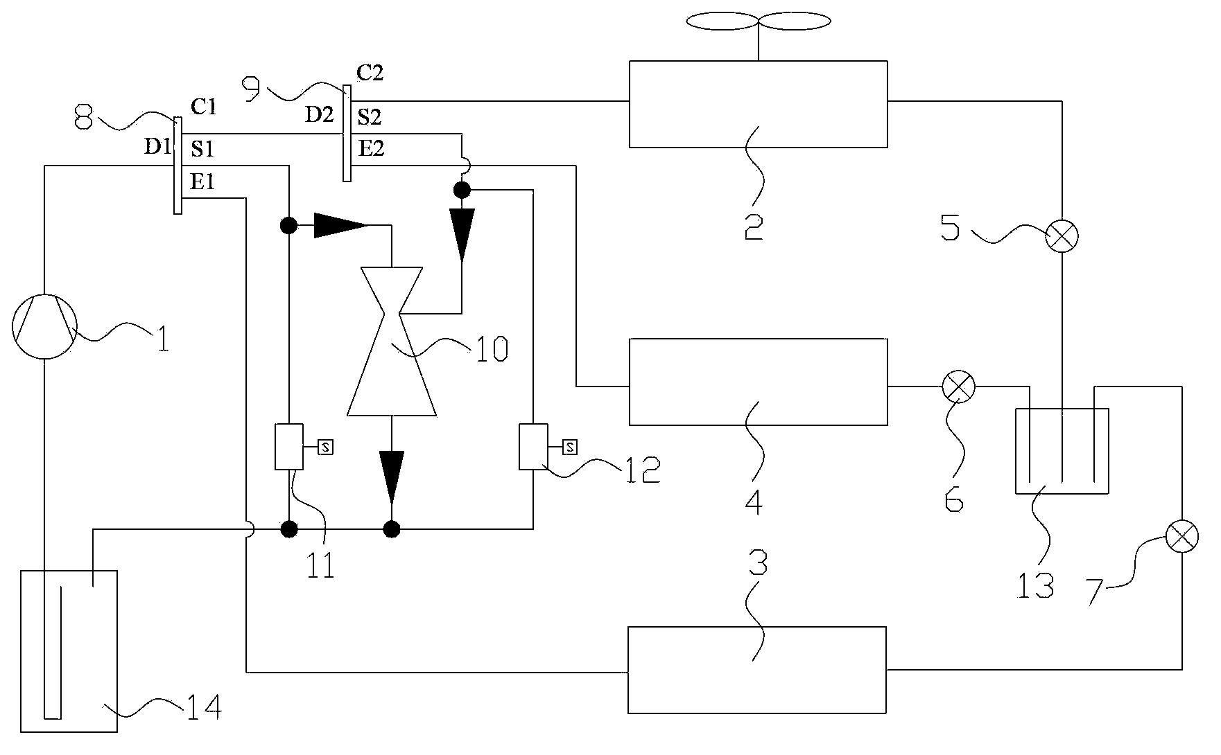
[0117] like figure 2 shown, will figure 1 After the positions of the high and low temperature heat exchangers are exchanged, the connection modes of the first four-way valve 8 and the second four-way valve 9 and the injector 10 are also changed accordingly, forming a new system connection diagram. figure 2 The reference numerals in are the same as the components represented by the reference numerals in the first embodiment. The principle of the second embodiment is similar to that of the first embodiment, and will not be described again.

[0118] As can be seen from the above description, the above-mentioned embodiments of the present invention have achieved the following technical effects:

[0119] An independent control of temperature and humidity is realized on a set of air-conditioning systems, so that different grades of energy can be fully utilized, which not only improves energy utilization, but also improves the comfort of air-conditioned rooms. The introduction o...


PUM


Abstract

The invention provides an air-conditioning system. The air-conditioning system comprises a compressor, two four-way valves, a condenser, two heat exchangers, an ejector, three throttling devices and two electromagnetic valves, wherein a first connector of the first four-way valve is communicated with an exhausting end of the compressor; a second connector of the first four-way valve is communicated with a first connector of the second four-way valve; a third connector of the first four-way valve is communicated with an injection opening of the ejector; a fourth connector of the first four-way valve is communicated with the low-temperature heat exchanger; a second connector of the second four-way valve is communicated with the condenser; a third connector of the second four-way valve is communicated with an entrance port of the ejector; a fourth connector of the second four-way valve is communicated with the high-temperature heat exchanger; the condenser, the high-temperature heat exchanger and the low-temperature heat exchanger are communicated to one another through the first throttling device, the second throttling device and the third throttling device respectively; and an inlet of the compressor is communicated with the injection opening and the entrance port of the ejector through the first electromagnetic valve and the second electromagnetic valve respectively and is communicated with an outlet of the ejector. By using the air-conditioning system, the energy utilization rate can be increased, and the comfort level of a room is improved.

Description

technical field [0001] The present invention relates to the field of air conditioning, and more particularly, to an air conditioning system. Background technique [0002] In the prior art, an air-conditioning system generally adopts a temperature-humidity coupling control method. In summer, the condensation and dehumidification method (using chilled water at 7°C) is used to cool and dehumidify the air, and at the same time remove the sensible heat load and latent heat load of the building. In an air conditioning system, the sensible heat load accounts for about 50% to 70% of the total load, while the latent heat load accounts for about 30% to 50% of the total load. In the sensible heat load, the heat that can be exhausted by the high-temperature cold source is used together with the dehumidification to share the low-temperature cold source of 5-7 °C for processing, resulting in a waste of energy utilization quality. Moreover, although the humidity of the air after condensa...

Claims


Application Information

Patent Timeline
Patent Type & Authority Applications(China)
IPC IPC(8): F25B13/00F25B9/08F25B41/04F25B41/06F25B41/20F25B41/34F25B41/385
Inventor 曹巍林海佳尚瑞黄玉优
Owner GREE ELECTRIC APPLIANCES INC
Learn More