
Rubber stripping and cutting machine

A peeling and cutting machine and rubber technology, which is applied in the direction of dust removal, metal processing, and separation of dispersed particles. It can solve the problems of dust affecting the yield rate, affecting work efficiency, and affecting the thickness of finished products. It achieves high precision of screw transmission and simple operation. Convenience and the effect of improving work efficiency

Active Publication Date: 2014-05-28
广东博森新材料有限公司
View PDF6 Cites 9 Cited by
  • Summary
  • Abstract
  • Description
  • Claims
  • Application Information

AI Technical Summary

Problems solved by technology

There are the following defects in the production process of traditional technology: 1) The fixed blade has a small adaptability range, and can only peel and cut waste rubber with a hardness higher than 50 degrees, but cannot peel and cut waste rubber that is too soft; 2) If the fixed blade encounters a Sand, stone, metal wire and other hard materials, the blade is prone to chipping. After the chip is chipped, it needs to be shut down to remove the blade and then re-grinded with an external grinder, which affects work efficiency and affects the yield; 3) Using an external When the grinding machine is used for grinding, a large amount of dust pollution and waste water pollution will be generated, which will have an impact on the environment; 4) Each station needs to be equipped with an operator, and at least 5 operators must be allocated when the entire equipment works synchronously, which wastes manpower and data; 5) The propulsion accuracy of the hanging wheel propulsion device is not high, which affects the thickness of the finished product, and requires frequent adjustments to determine the accuracy

Method used


Image

  • Rubber stripping and cutting machine
  • Rubber stripping and cutting machine
  • Rubber stripping and cutting machine

Examples


Embodiment Construction

[0034] The present invention will be further described in detail below in conjunction with the accompanying drawings and specific embodiments.

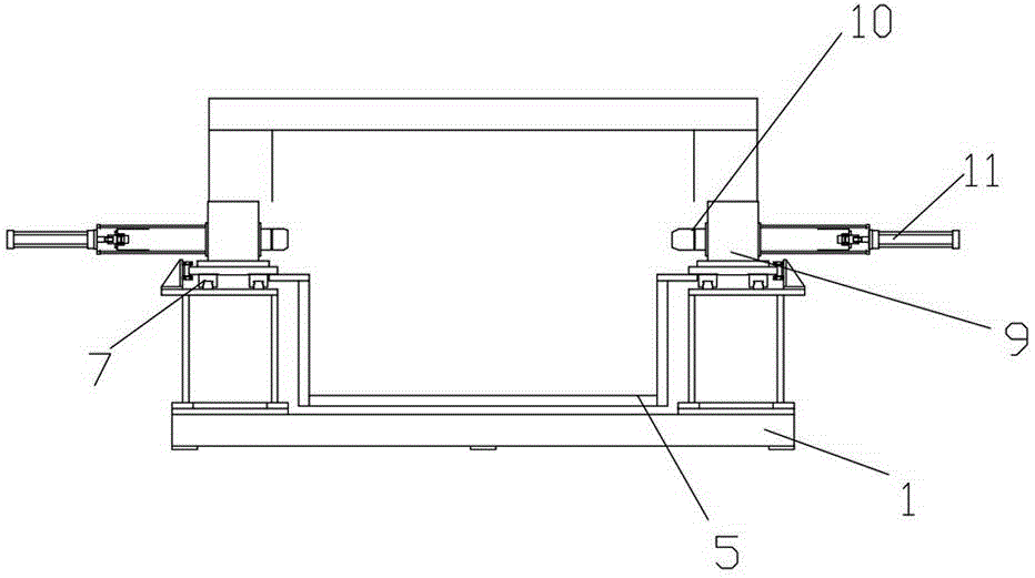
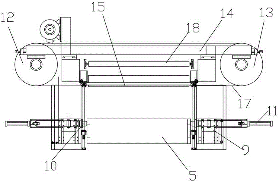
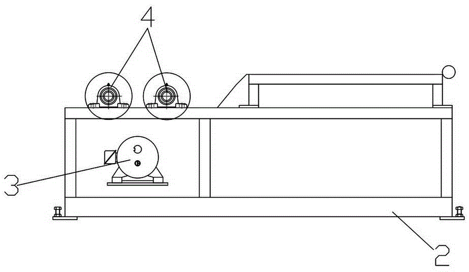
[0035] In this embodiment, refer to Figure 1 ~ Figure 4The specific implementation structure of the rubber peeling and cutting machine includes a frame-type base 1 and a propulsion device 5 installed on the base 1, a feeding device 9 and a dynamic blade device, and an independent winding material device and a control electric box are connected externally, and the control The electric box includes a PLC control system and an operation panel, and the operation panel includes a parameter setting panel, a start button, a stop button and an emergency stop button. The thickness value of the stripped and cut rubber coil can be directly set on the parameter setting panel, so as to automatically adjust the propulsion value of the propulsion device 5 and the rotating speed of the feeding device 9 through the program of the PLC control syst...


PUM


Abstract

The invention discloses a rubber stripping and cutting machine in the field of rubber manufacturing equipment. The rubber stripping and cutting machine comprises a frame-type base, a boosting device, a feeding device and a dynamic blade device and is externally connected with an independent material coiling device and a control electric box, wherein the boosting device, the feeding device and the dynamic blade device are mounted on the base, the boosting device is disposed at the rear end of the base and boosts the base forwards via a screw transmission mechanism, the dynamic blade device is disposed in front of the boosting device and comprises a driving wheel, a driven wheel, a cutter rest, a driving motor for driving the driving wheel and a soft blade for connecting the driving wheel with the driven wheel, and when the boosting device boosts forwards, a rubber coil driven to rotate by the feeding device contacts with a blade edge of the soft blade so as to be laterally stripped and cut by the soft blade rotating at a high speed. The dynamic blade device is added, stripping and cutting precision is higher, the soft blade rotating at the high speed can strip and cut rubber in a wider hardness range, and the rubber stripping and cutting machine is applicable to all waste rubber materials.

Description

[0001] technical field [0002] The invention relates to the field of rubber production equipment, in particular to a rubber stripping and cutting machine. [0003] Background technique [0004] In the production process of rubber flooring, it is necessary to use a stripping machine to peel and cut layer by layer, so as to produce a certain thickness of sheet rubber flooring. The traditional rubber peeling and cutting machine consists of a fixed blade, a hanging wheel propulsion device, a feeding device and a receiving device. There are the following defects in the production process of traditional technology: 1) The fixed blade has a small adaptability range, and can only peel and cut waste rubber with a hardness higher than 50 degrees, but cannot peel and cut waste rubber that is too soft; 2) If the fixed blade encounters a Sand, stone, metal wire and other hard materials, the blade is prone to chipping. After the chip is chipped, it needs to be shut down to remove the...

Claims


Application Information

Patent Timeline
IPC IPC(8): B26D1/46B26D7/06B26D7/12B26D5/00B26D7/26B08B15/04B01D46/02
Inventor 郭富华
Owner 广东博森新材料有限公司
Learn More