Discharge dose accurate control method and device applied to cardiac defibrillator

A precise control and defibrillator technology, applied in the field of medical electronics, can solve the problems of difficult individualized precise control, myocardial damage, increasing the design complexity and manufacturing cost of defibrillator equipment, etc.

Inactive Publication Date: 2014-05-28
UNIV OF ELECTRONIC SCI & TECH OF CHINA
View PDF9 Cites 7 Cited by
  • Summary
  • Abstract
  • Description
  • Claims
  • Application Information

AI Technical Summary

Problems solved by technology

Although the above patents and biphasic defibrillation waves are used, the positive phase and reverse phase are essentially only one wave, which is in the form of high-voltage exponential decay and decline.
Its main disadvantages are: (1) The energy control deviation is relatively large, and the energy released by the defibrillator is adjusted according to the chest impedance, which makes it difficult to achieve individualized and precise control, especially for patients with extremely high or low impedance; (2) Exponential wave The aisle of the peak part exceeds the defibrillation threshold, which wastes energy and is easy to generate excessive stimulation and damage the myocardium; (3) The peak part of the exponential wave requires a capacitor accumulator with a higher initial voltage and a defibrillator with a higher withstand voltage requirement. Fibrillation output stage, increasing the design complexity and manufacturing cost of defibrillator equipment

Method used


Image

  • Discharge dose accurate control method and device applied to cardiac defibrillator
  • Discharge dose accurate control method and device applied to cardiac defibrillator
  • Discharge dose accurate control method and device applied to cardiac defibrillator

Examples


Embodiment Construction

[0039] The present invention is further set forth below in conjunction with the preferred embodiment shown in accompanying drawing:

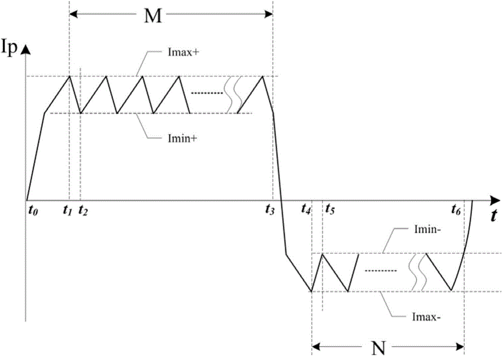
[0040] Refer to attached figure 1 , the discharge output waveform of the defibrillator in the preferred embodiment of the present invention is a biphasic sawtooth rectangular pulse waveform, which provides a defibrillation discharge current Ip in the form of a sawtooth fine wave superimposed on the biphasic rectangular wave to the ventricular myocardium in fibrillation, The forward and reverse discharge pulses consist of M(t 1 ~t 3 ) and N(t 4 ~t 6 ) sawtooth fine waves; z have the same peak amplitude range of each sawtooth wavelet, the same amplitude of the sawtooth wavelet between the forward and reverse pulses, the positive phase current reference interval Imax+~Imin+, and the reverse phase Imax-~Imin-.

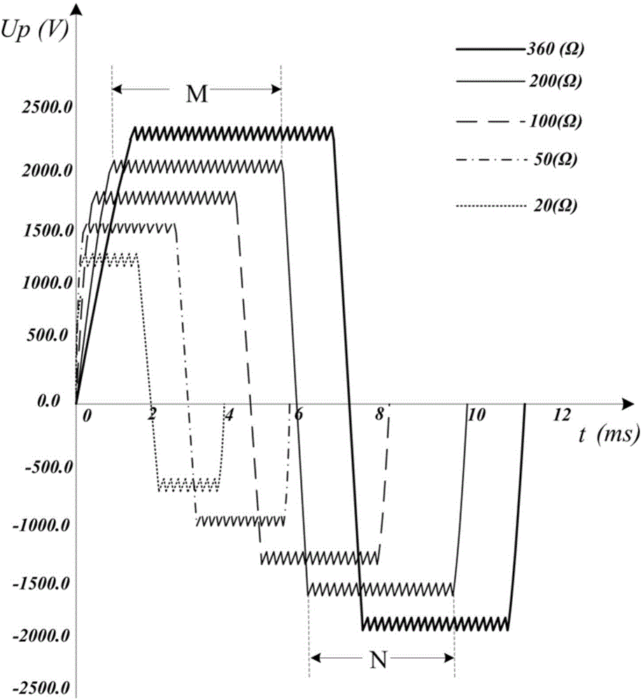
[0041] Refer to attached figure 2 , to further elaborate figure 1 The individualized discharge dose control for different patients i...


PUM


Abstract

The invention provides a discharge dose accurate control method and device applied to a cardiac defibrillator. The defibrillator automatically sets the minimum electric energy required by defibrillating discharge according to the magnitude of sensed thoracic impedance. The amplitude reference interval value and the normal phase and reverse phase sawtooth wave total number of a dual phase sawtooth pulse discharge waveform are calculated. According to a preset H bridge switch control policy, the electric energy in an energy storage capacitor is used to carry out fast high voltage electric defibrillating on a patient in the form of dual phase sawtooth wave pulse. According to the invention, based on thoracic impedance sensing of the patient and individually customized dual phase sawtooth pulse discharge, defibrillating discharge current which is superposed on a dual phase rectangular wave and is in the form of a sawtooth fine wave is provided for heart in a ventricular fibrillation state; by controlling the normal phase and reverse phase sawtooth wave number, the patient discharge dose is accurately and flexibly controlled, which is conducive to improving the defibrillating discharge individual pertinence and the success rate of once defibrillating; and by reducing the high voltage amplitude, myocardial damage in a defibrillating process is effectively reduced.

Description

technical field [0001] The invention belongs to the technical field of medical electronics, and in particular relates to a discharge dose control method for cardiac defibrillation, in particular to an accurate defibrillation discharge dose based on a biphasic sawtooth square wave output bridge used in an automatic external defibrillator (AED). Control Method. Background technique [0002] Sudden cardiac death (SCD) is an unexpected circulatory collapse that occurs immediately within 1 hour of clinical symptoms, leading to cardiac arrest, and is the main cause of death from cardiovascular diseases. The epidemiological research results of the Center for Health Statistics in the United States show that more than 50% of all cardiovascular disease deaths are SCD, and the total number of SCD cases in my country is more than 544,000 cases every year; at the same time, in the past few decades, with the aging of the population The occurrence of process SCD has an upward trend. Among...

Claims


Application Information

Patent Timeline
IPC IPC(8): A61N1/39
Inventor 赖大坤
Owner UNIV OF ELECTRONIC SCI & TECH OF CHINA
Why Eureka
Try Eureka